01
Background
The Marine Academy of Science and Technology, my high school I graduated from in 2012, has helped me get to where I am today. Through Technology, AutoCAD Classes, and Systems Engineering I and II, they've inspired me to do the things I strive for today. In return, I wanted to give back to my school, and help the students engage more deeply into their academics. The best way I thought of doing this was to build MAST a 3D Printer. This will allow students to print their designs, build custom parts, see their technical drawings come to life. It will also be very professional for presentations which may lead to additional funding, perpetually improving the quality of education. This is my build log.
02
Photos
Laser Cutting the Acrylic for High Resolution Frame
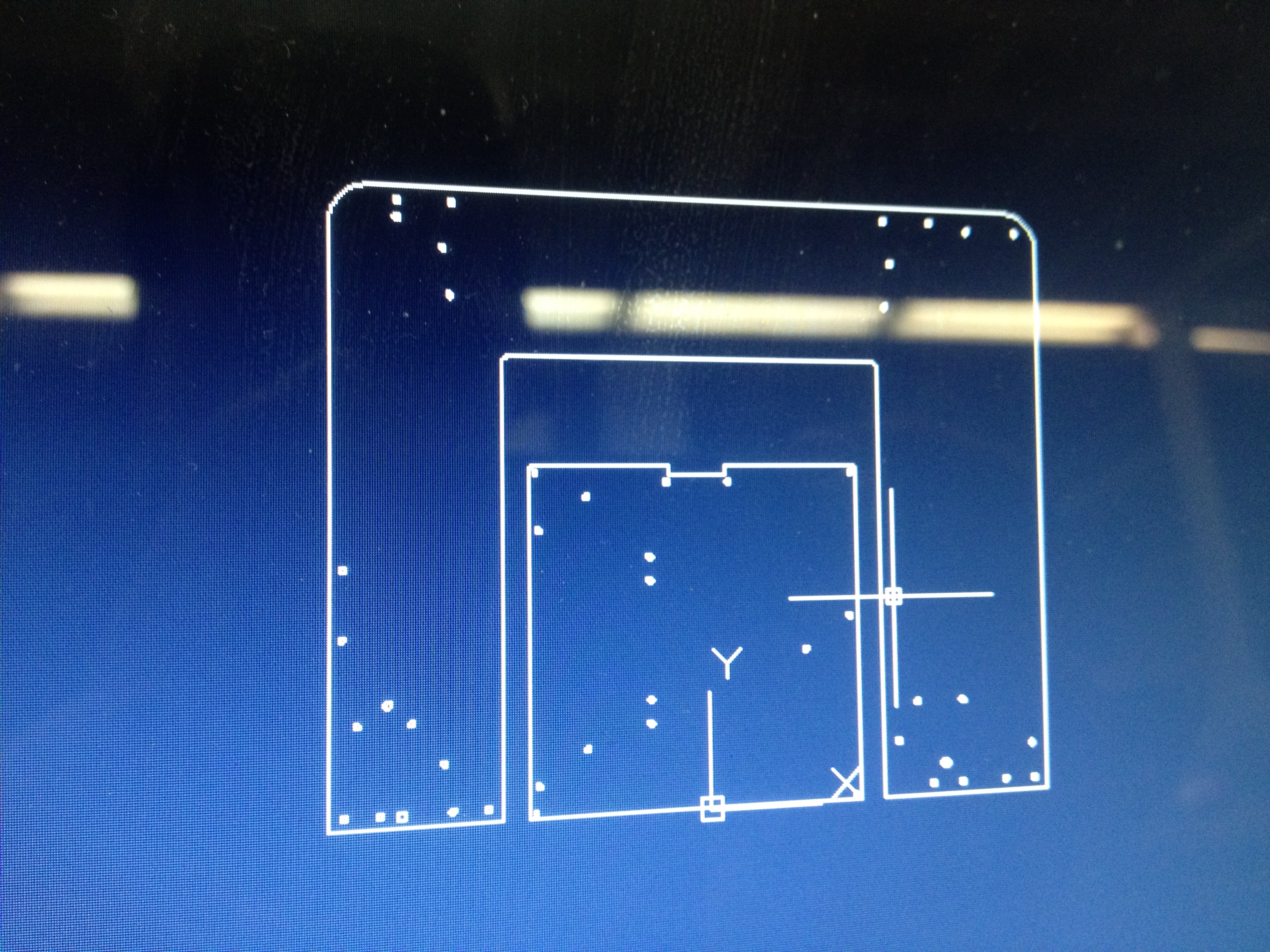
Laser Cutting the Acrylic for High Resolution Frame
Frame Successfully Cut.
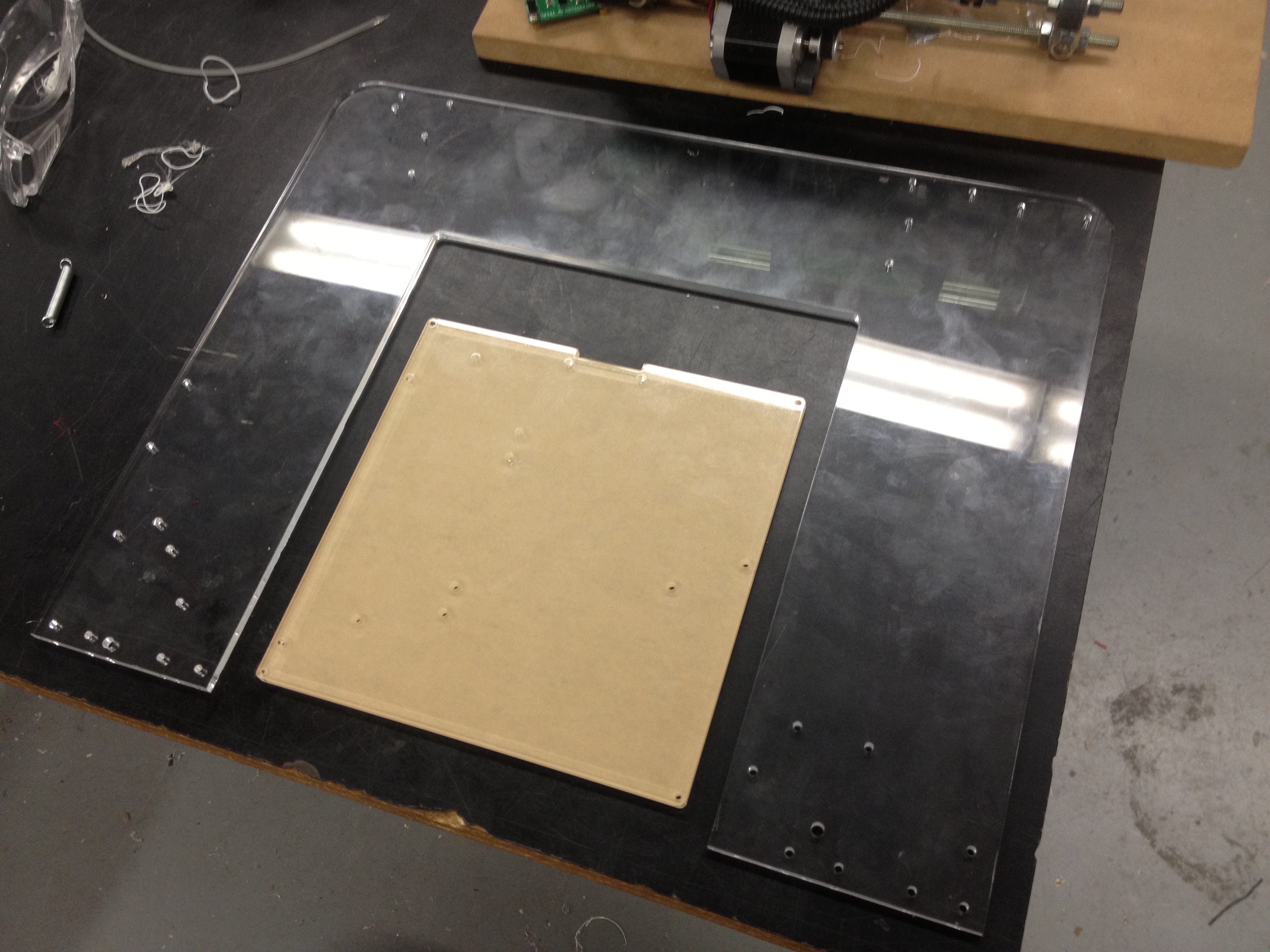
Frame Successfully Cut.
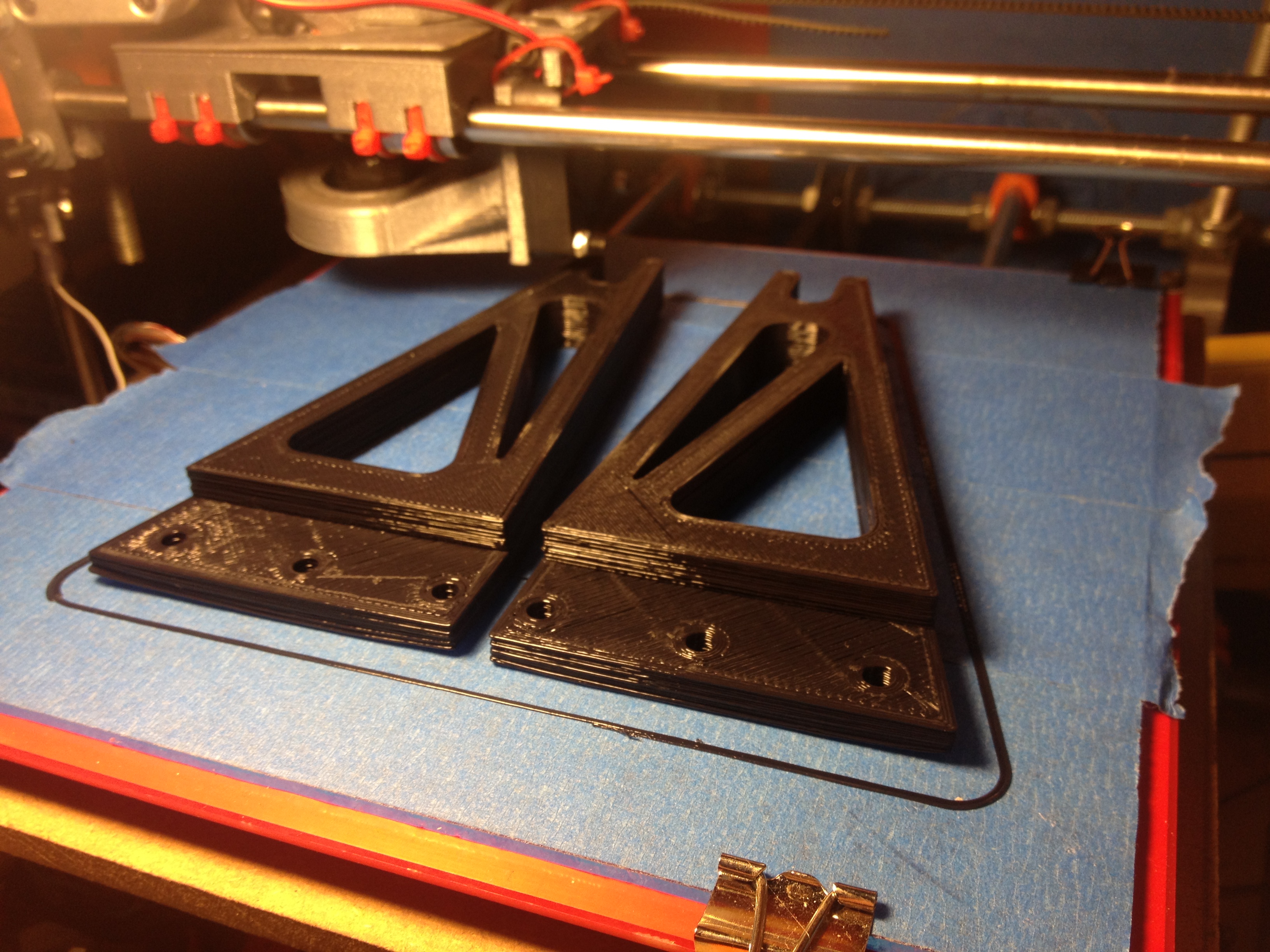
Printing out Right angle Brackets.

Printing out Right angle Brackets.
Pronterface showing toolpath instructions for 3D Printer.
Pronterface showing toolpath instructions for 3D Printer.
Printing out the X-Axis Idler. This shows the nice calibration of my Prusa i2, the first layer is very clean.
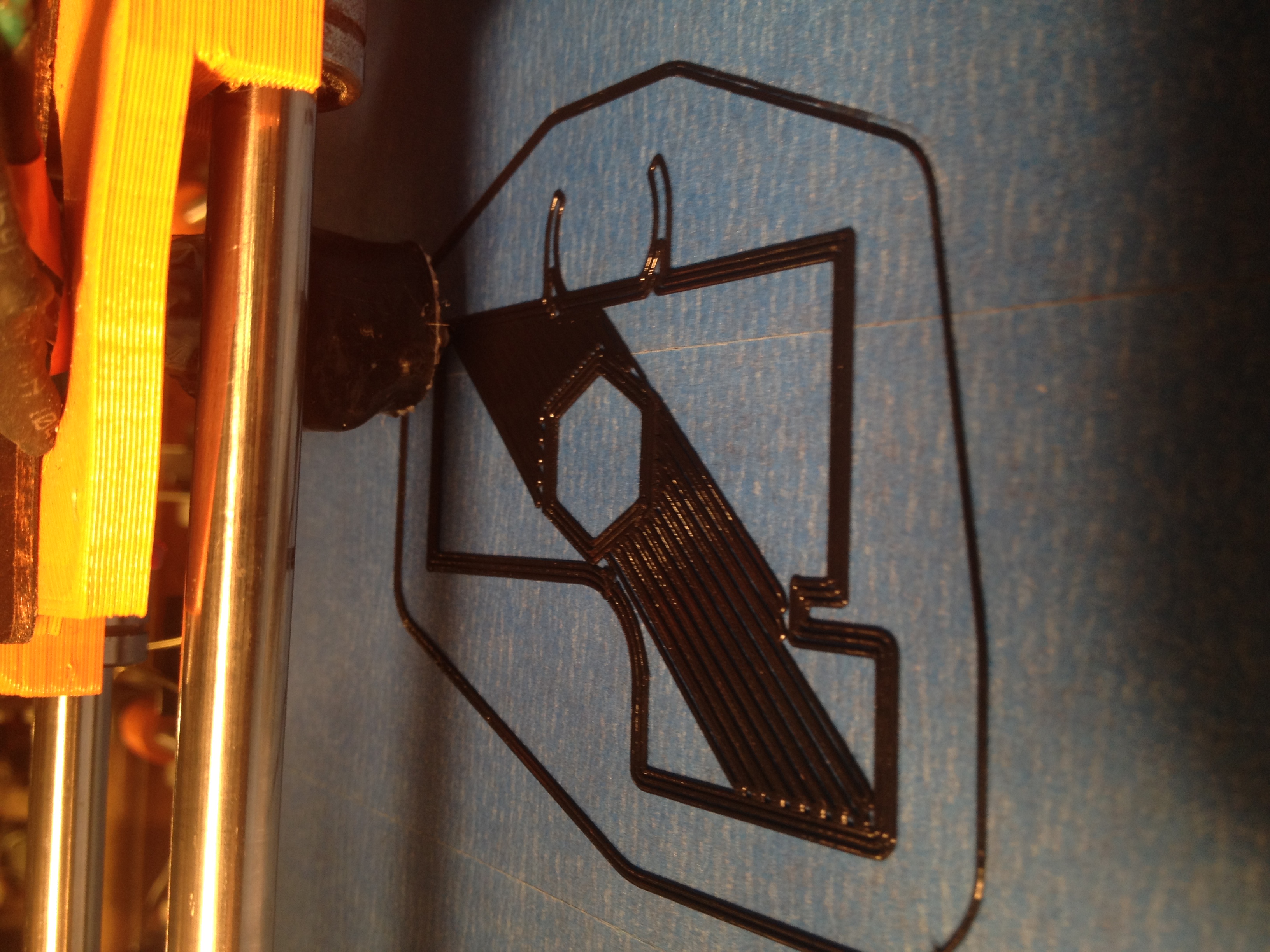
Printing out the X-Axis Idler. This shows the nice calibration of my Prusa i2, the first layer is very clean.
X-Idler nearly finished printing in beautiful quality.
X-Idler nearly finished printing in beautiful quality.
X-Idler up close in propert lighting.
X-Idler up close in propert lighting.
Linear Bearings pressed into the Plastic
Linear Bearings pressed into the Plastic
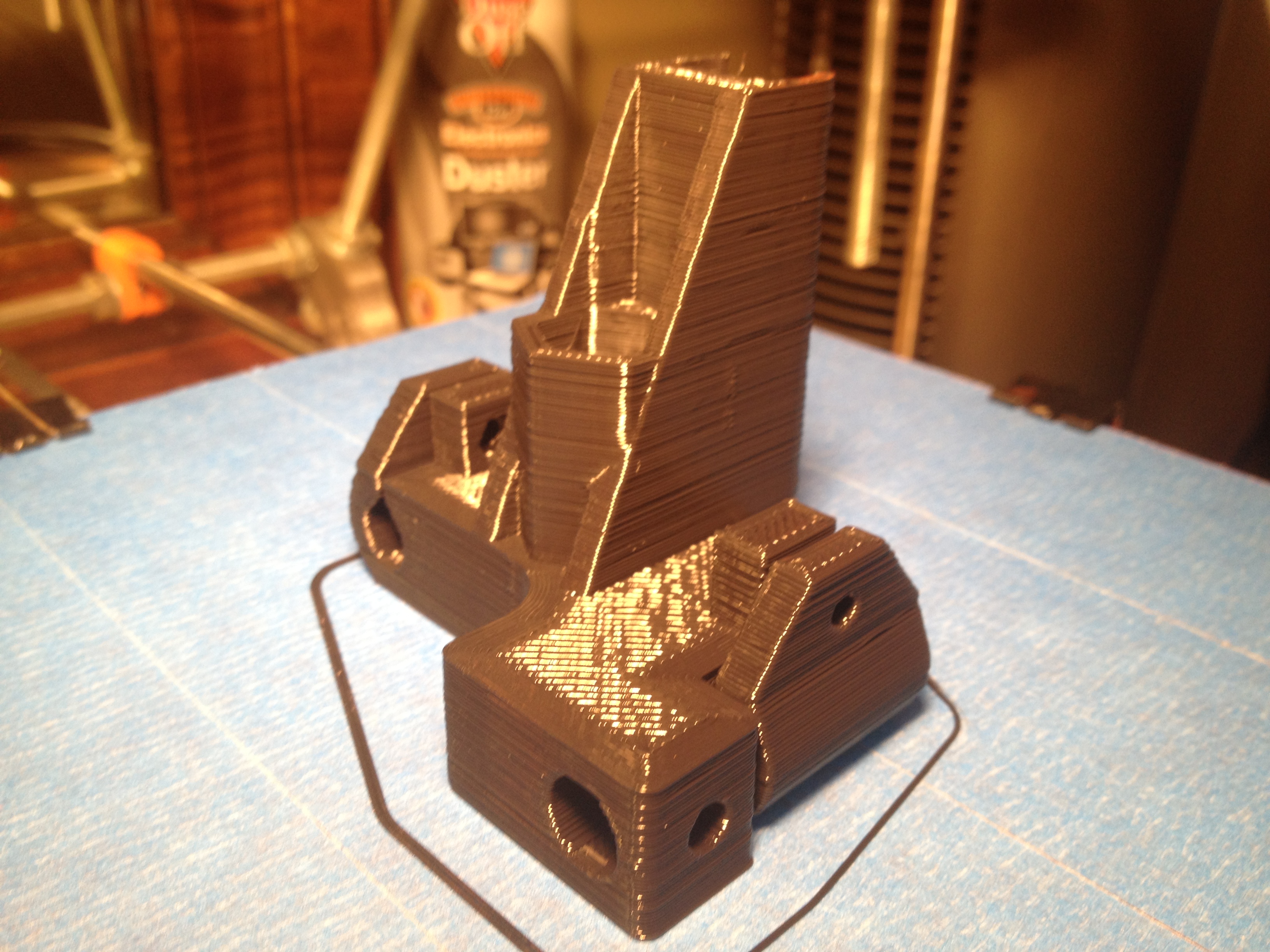
Various Components printed on my Prusa i2
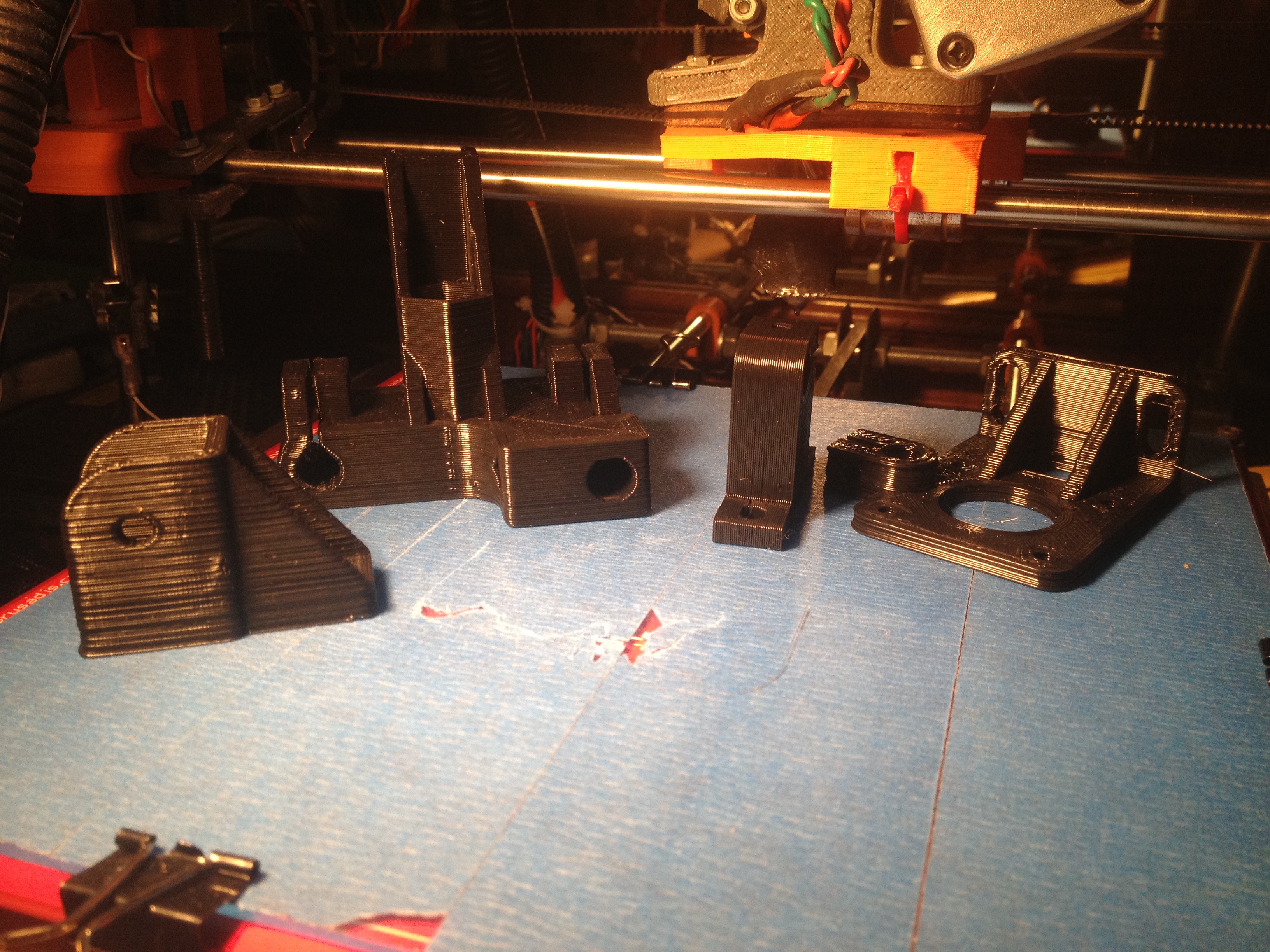
Various Components printed on my Prusa i2
Working on the Wade's Extruder Block.
Working on the Wade's Extruder Block.
Printing out the X-Carriage which will support the Extruder Block
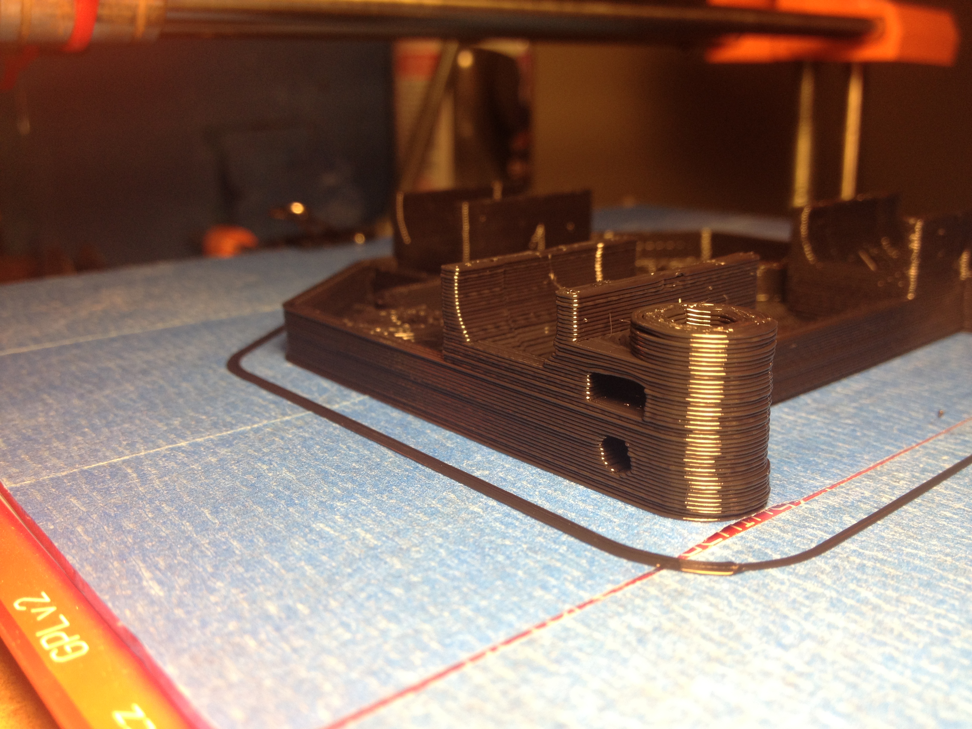
Printing out the X-Carriage which will support the Extruder Block
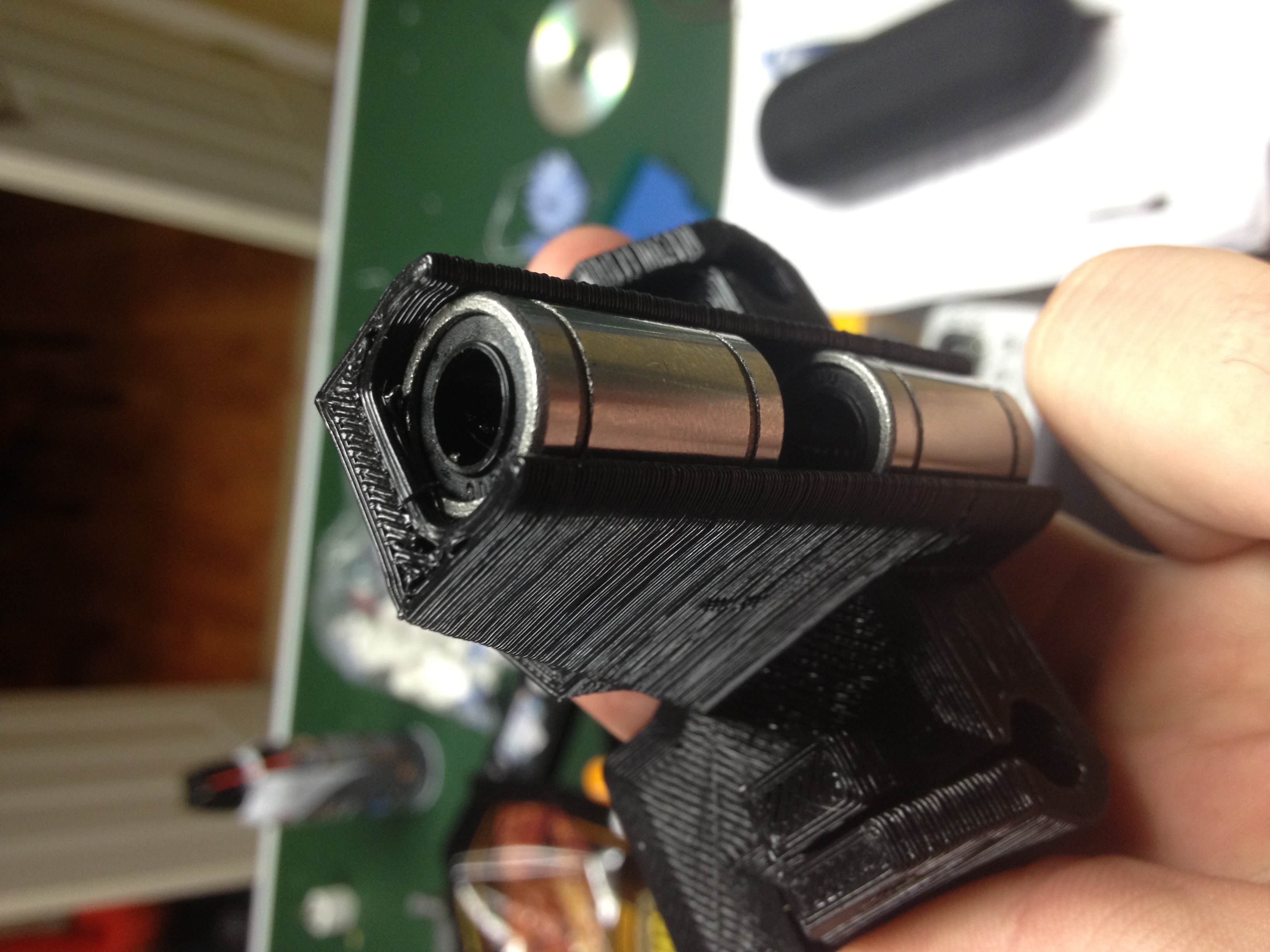
Linear Bearings secured onto the X-Carriage
Linear Bearings secured onto the X-Carriage
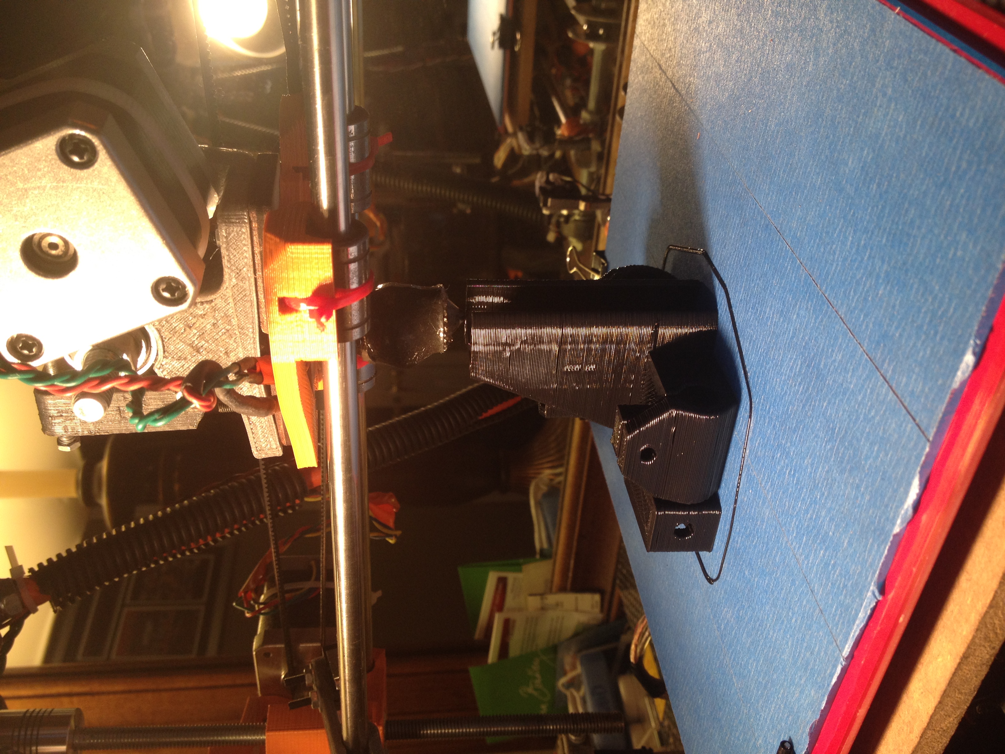
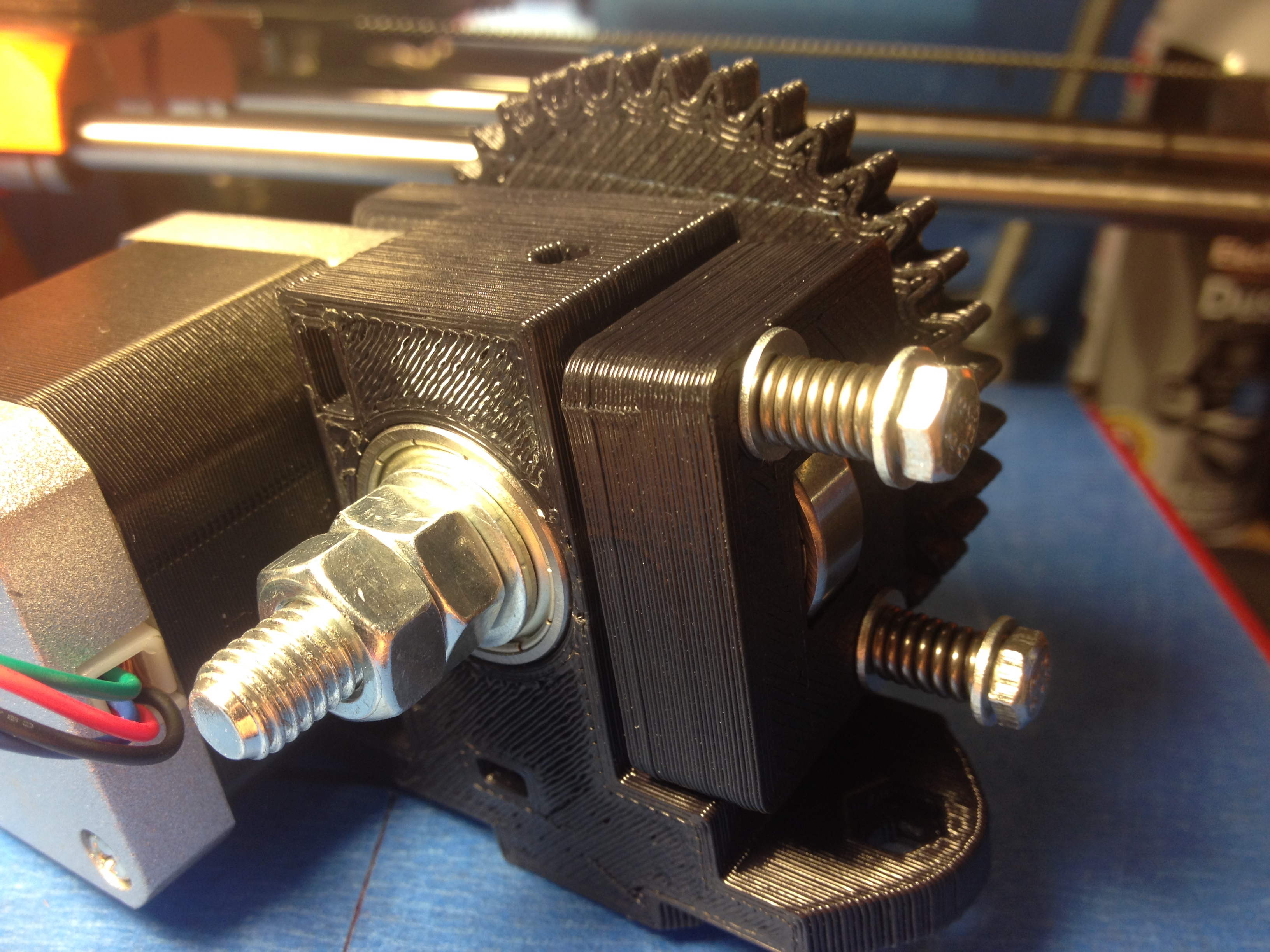
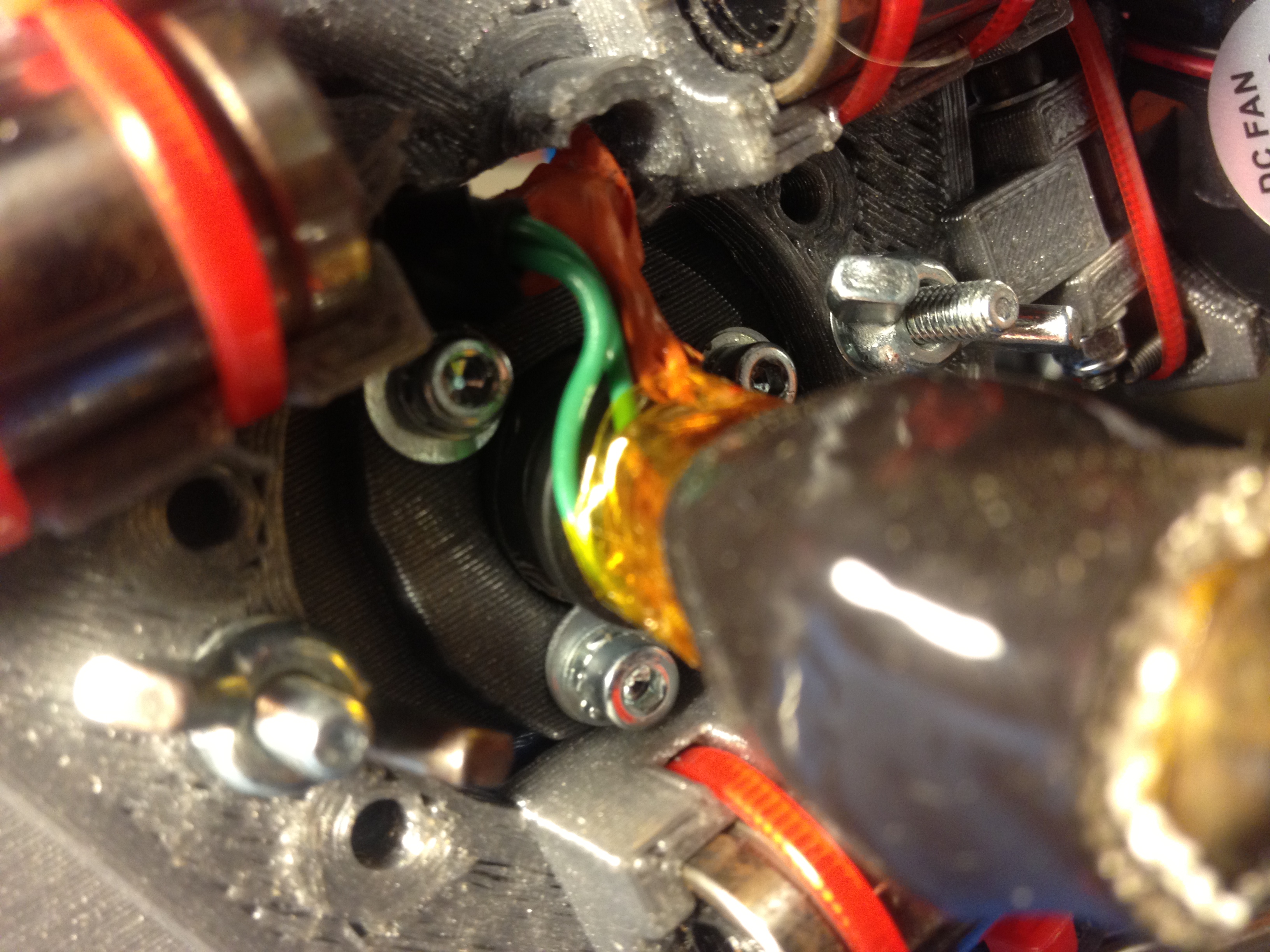
X-Motor Mount assembled w/ Linear Bearings and Stepper Motor.
X-Motor Mount assembled w/ Linear Bearings and Stepper Motor.
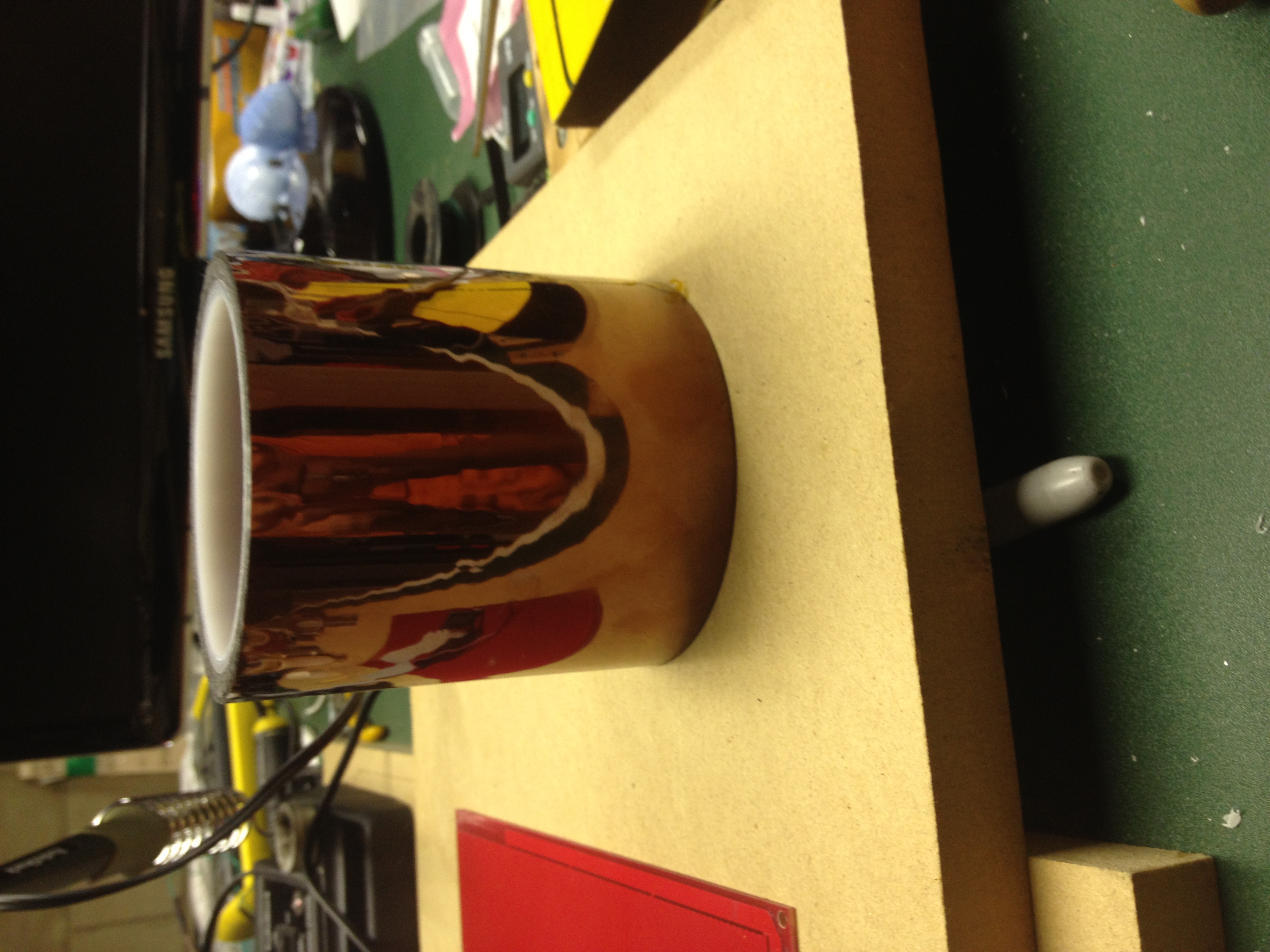
Heated Bed (12V 11A) over Aluminum Foil Tape to Reflect Infrared Radiation (Heat Insulator). Cardboard Insulator is used as well.
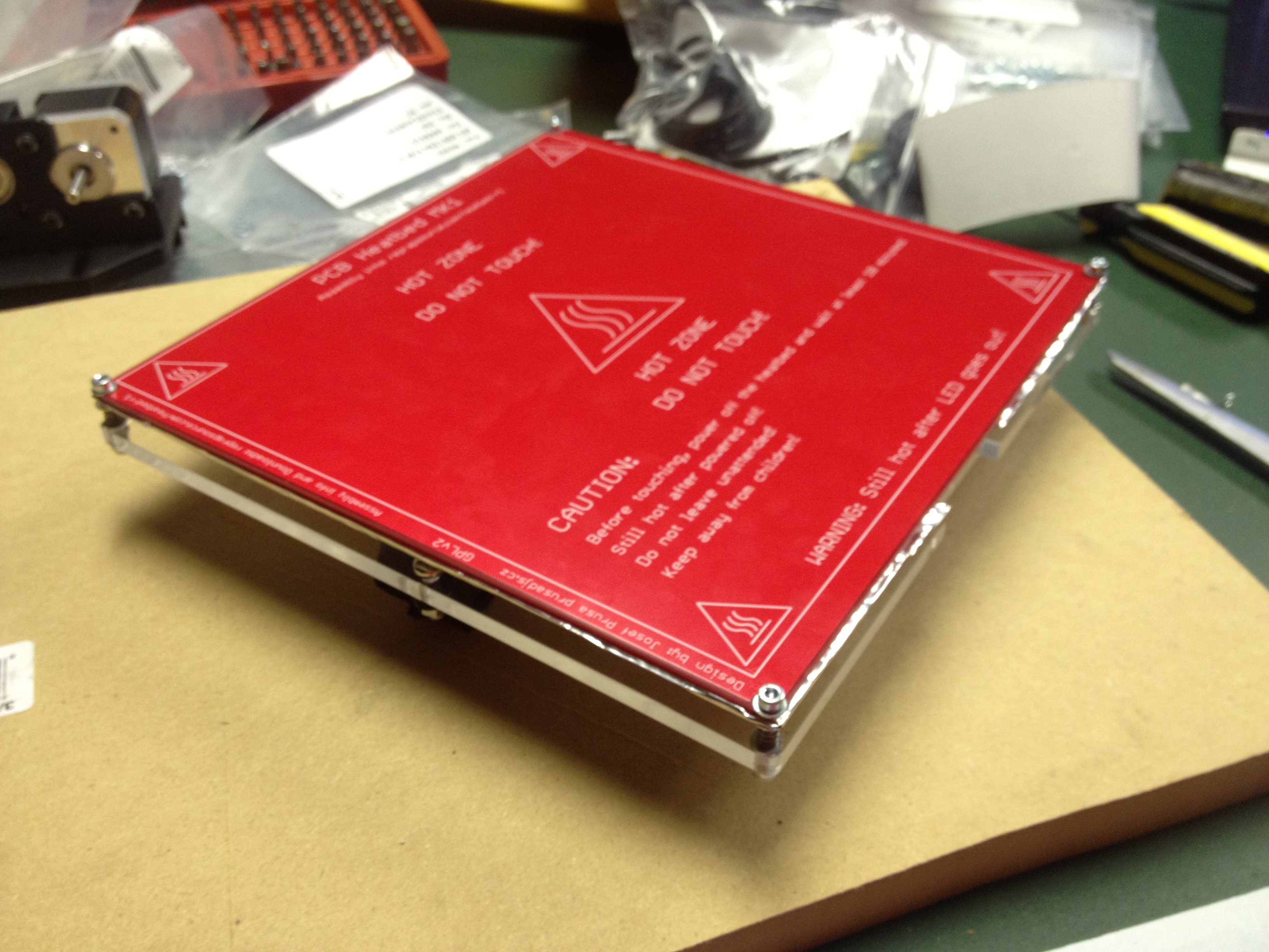
Heated Bed (12V 11A) over Aluminum Foil Tape to Reflect Infrared Radiation (Heat Insulator). Cardboard Insulator is used as well.
Underneath the Print-bed, 3 Bearings, small cutout in Aluminum foil for Wiring.
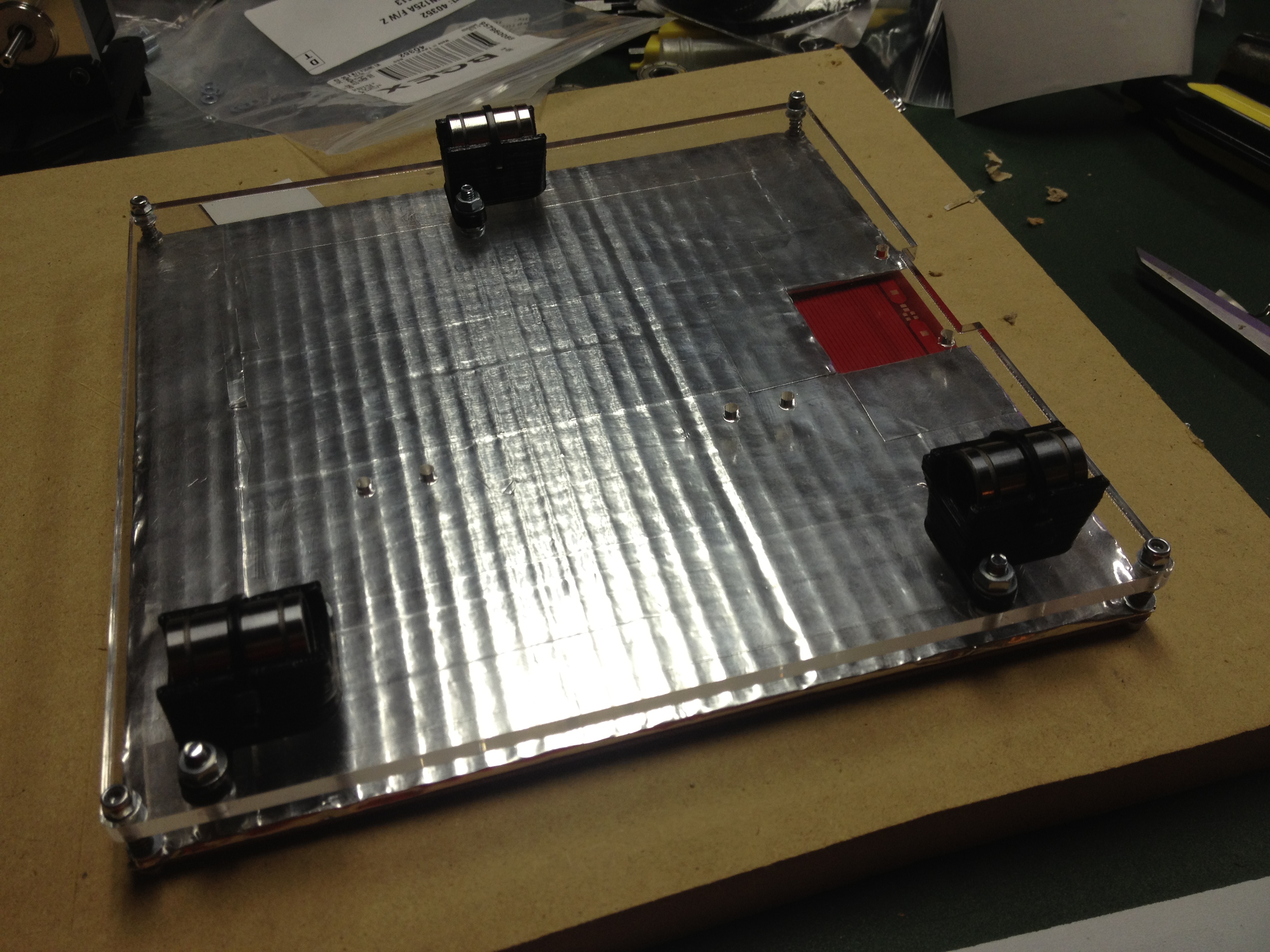
Underneath the Print-bed, 3 Bearings, small cutout in Aluminum foil for Wiring.
Brass Nozzle (0.5mm) with 36mm Brass Pipe (Drilled out) Connected to the Threaded Nozzle.
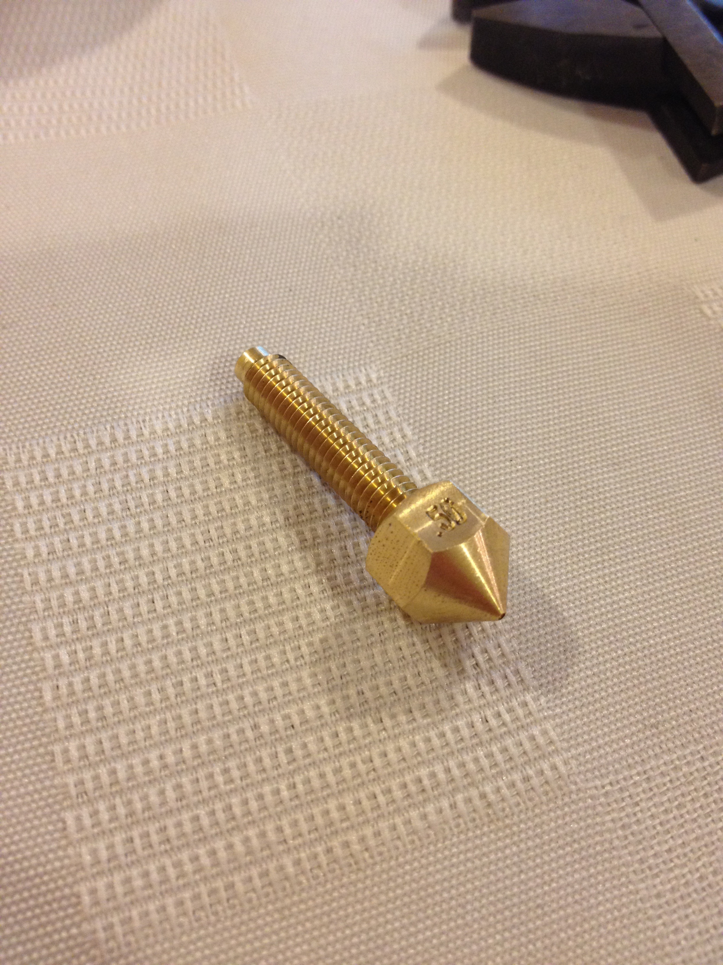
Brass Nozzle (0.5mm) with 36mm Brass Pipe (Drilled out) Connected to the Threaded Nozzle.
Creating the Ceramic Heat Core with Crimps and covering in layers of Ceramic Paste (To be cured in an Oven)
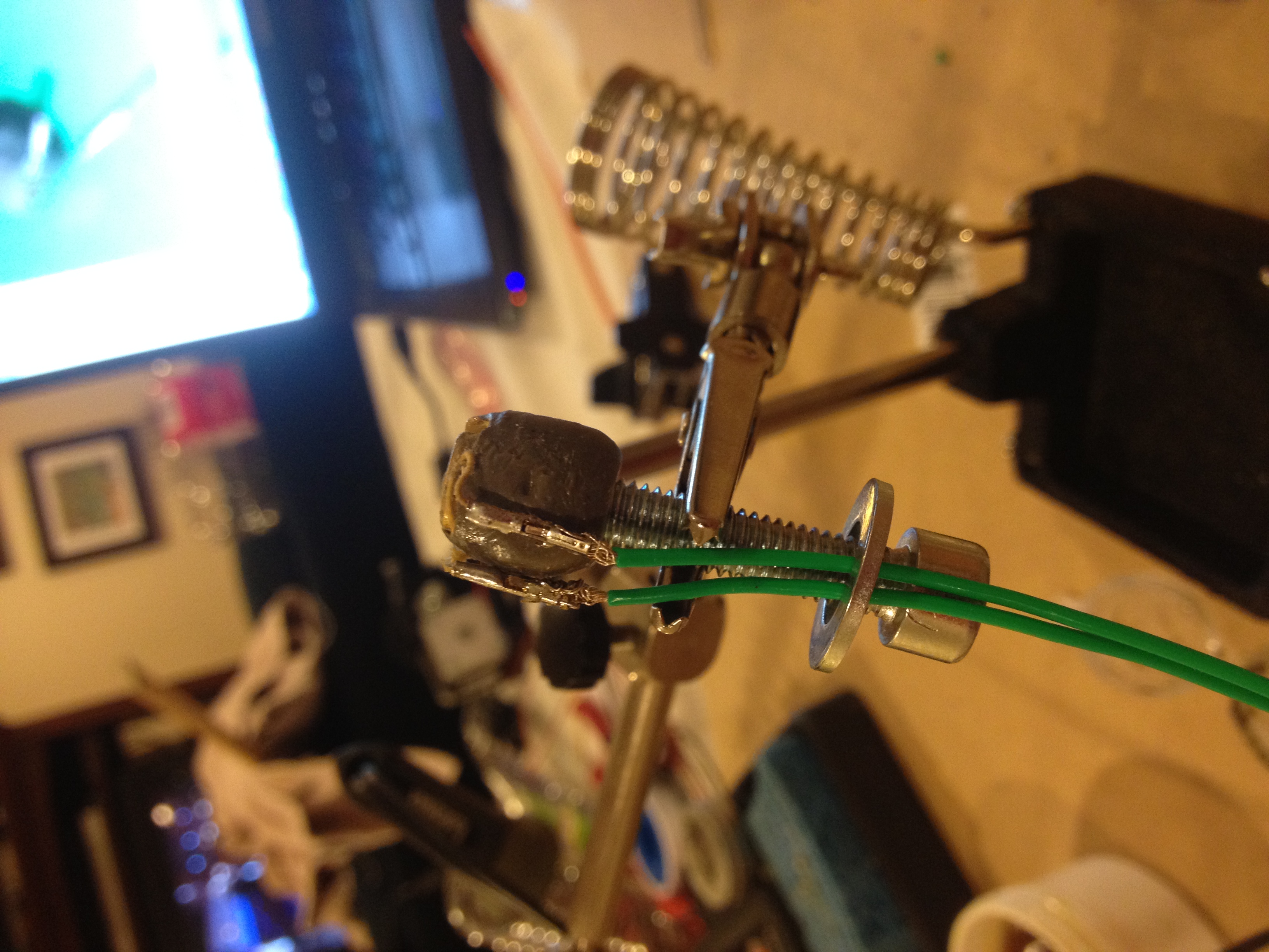
Creating the Ceramic Heat Core with Crimps and covering in layers of Ceramic Paste (To be cured in an Oven)
Printing out the Filament Spool Holders (for on top of Mendel90) on my Prusa i2 Printer.
Printing out the Filament Spool Holders (for on top of Mendel90) on my Prusa i2 Printer.
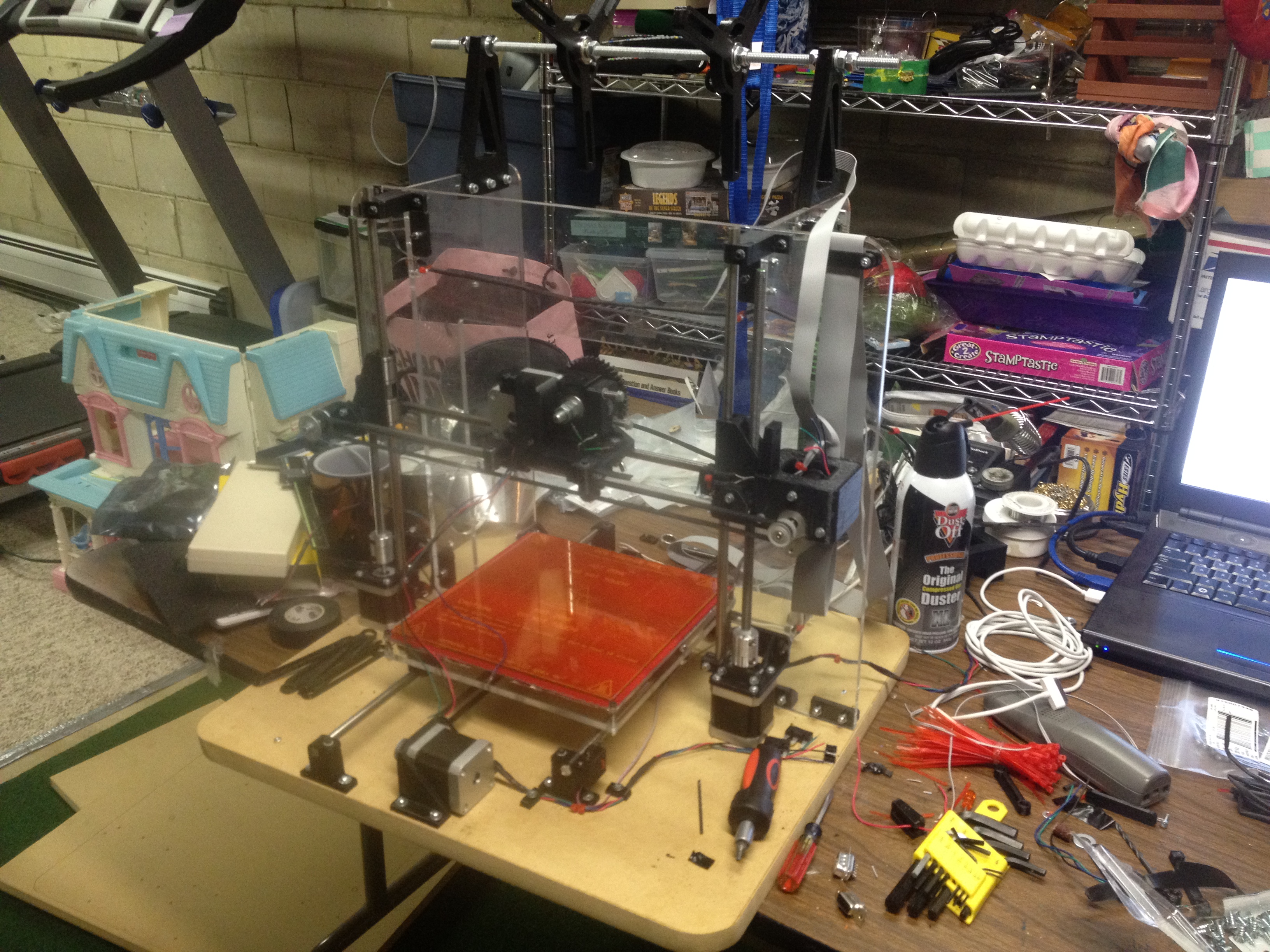
Testing Alignment of components on Medium Density Fiber Board (MDF) (3/4")
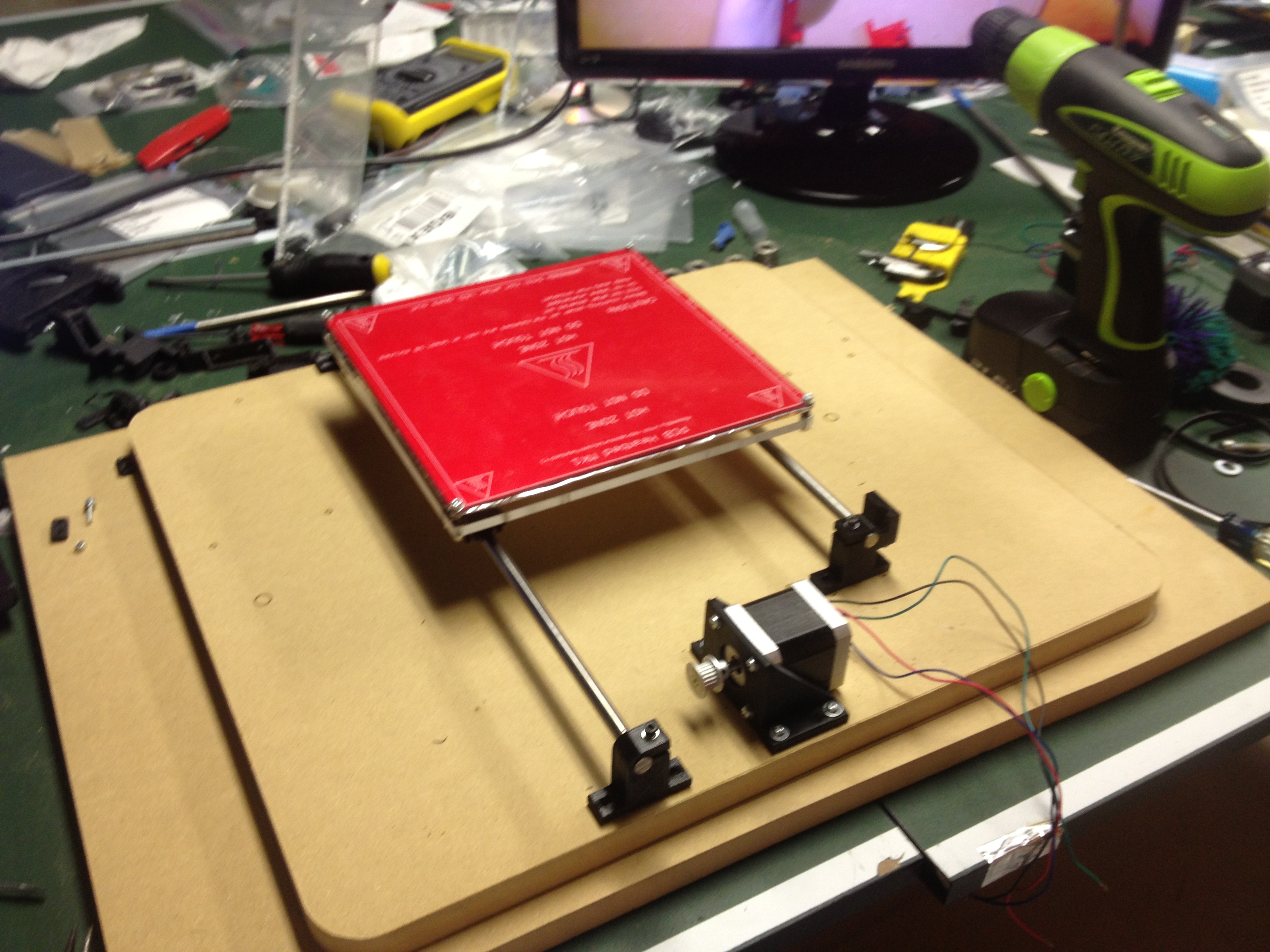
Testing Alignment of components on Medium Density Fiber Board (MDF) (3/4")
Orthogonal Acrylic Frame squared away using perpendicular printed mounts above. Y-Axis Secured and X-Axis Attached by Stainless Steel Round Bar.
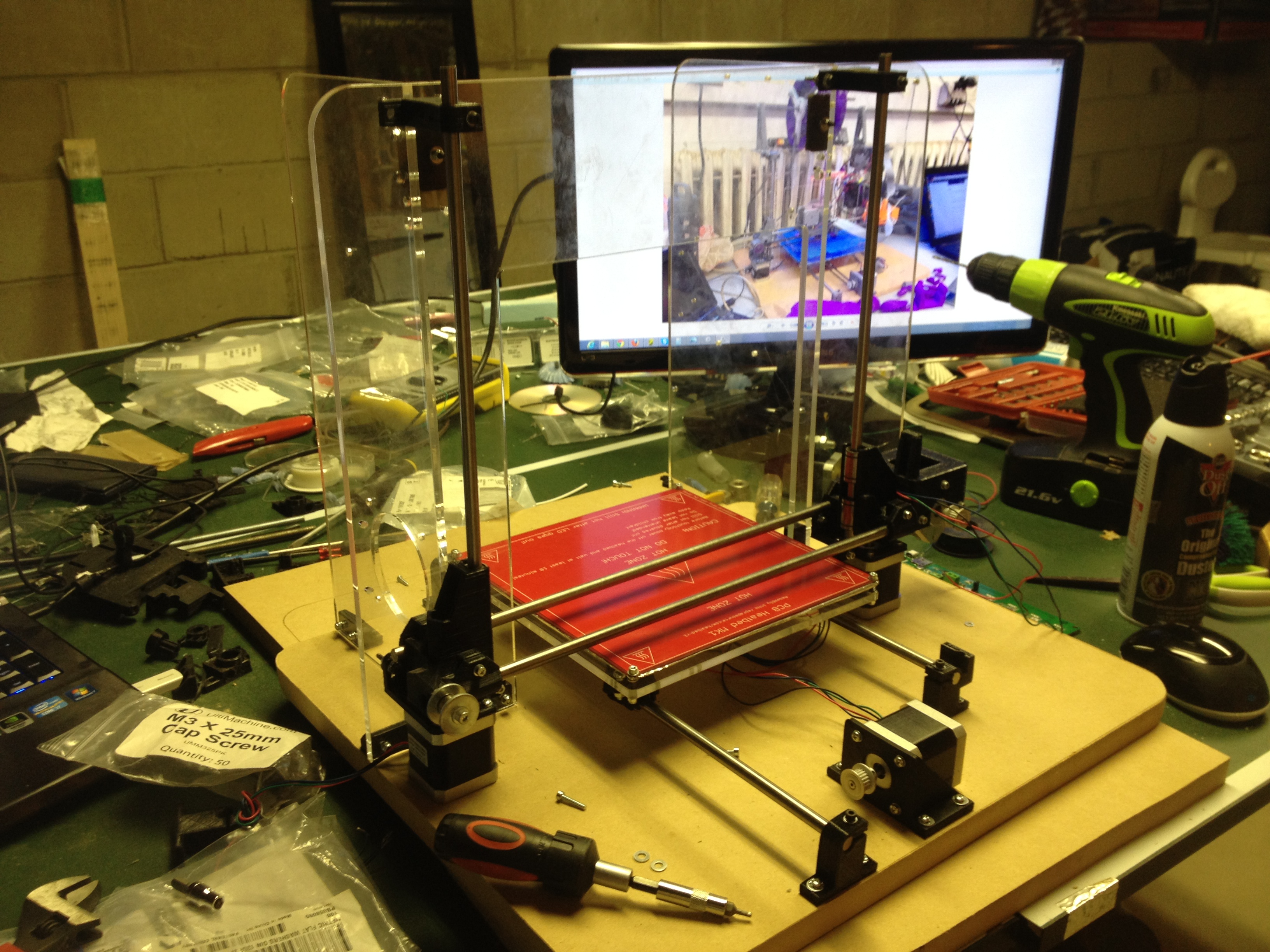
Orthogonal Acrylic Frame squared away using perpendicular printed mounts above. Y-Axis Secured and X-Axis Attached by Stainless Steel Round Bar.
Heated Bed Removed to Tension Y-Axis GT2 Belts.
Heated Bed Removed to Tension Y-Axis GT2 Belts.
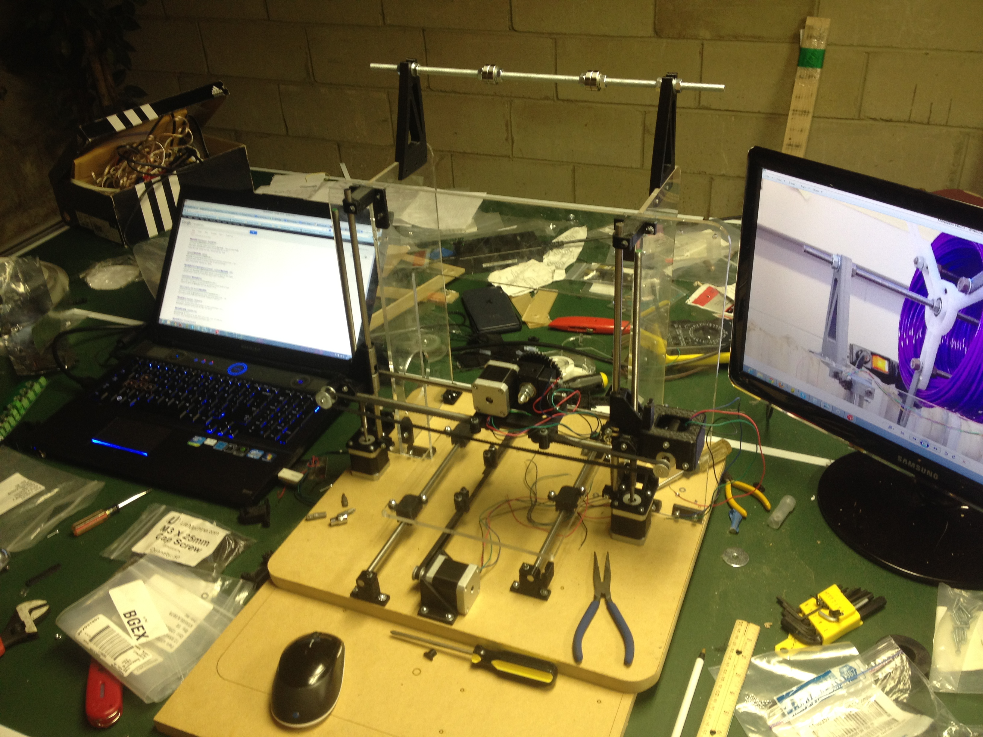
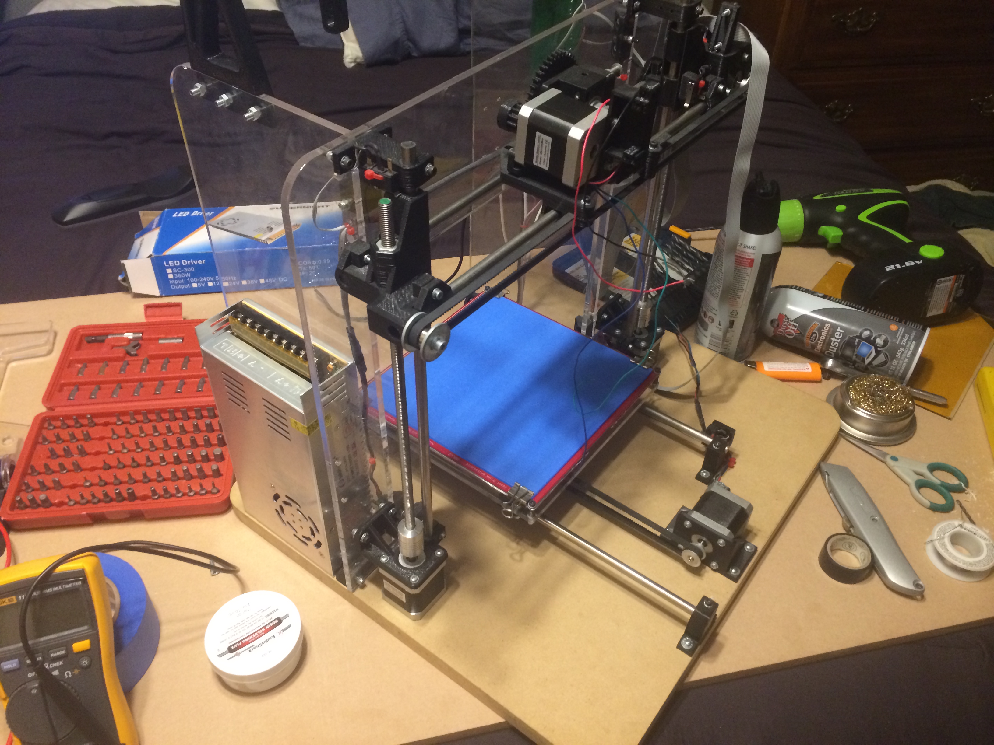
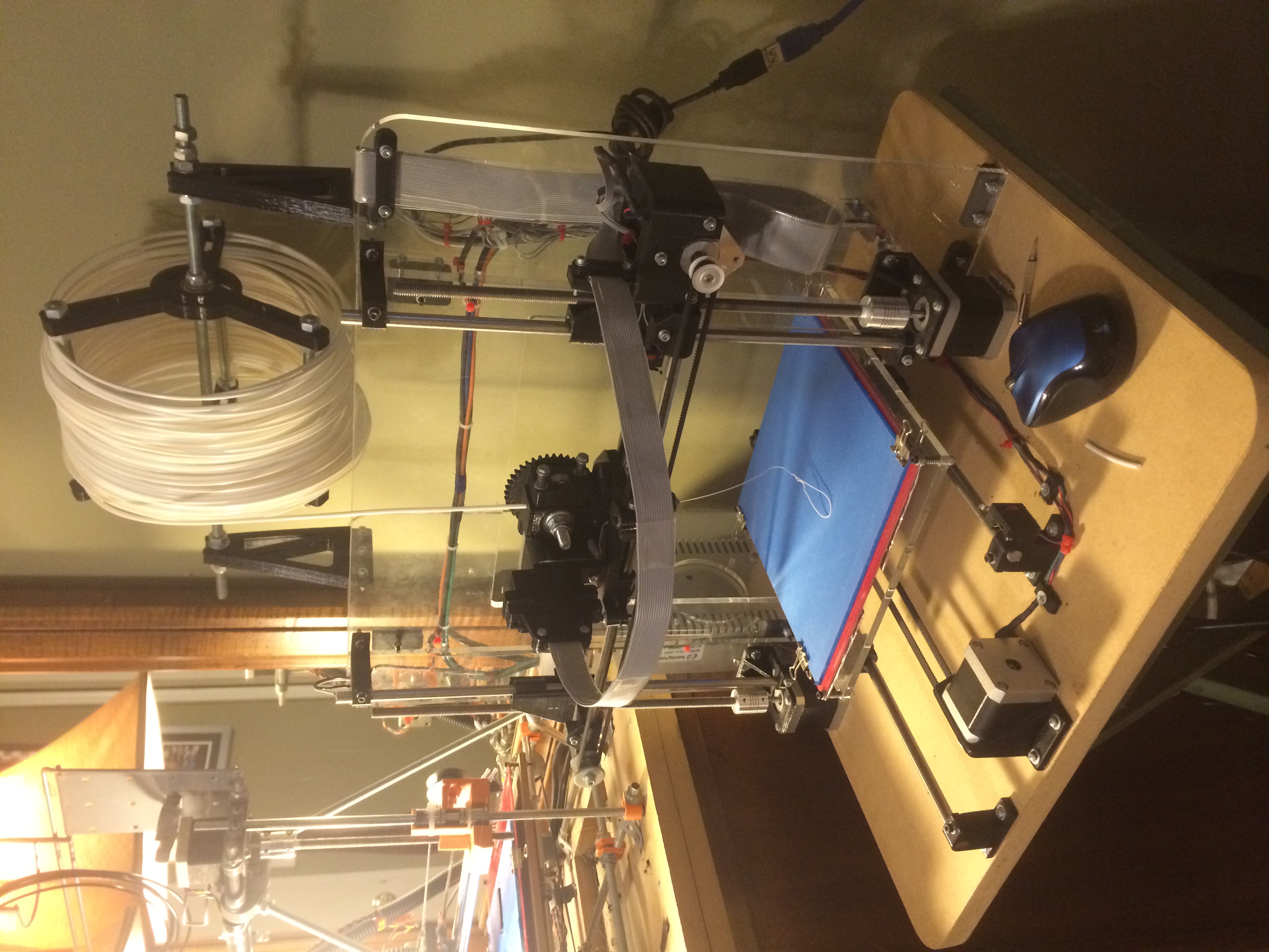
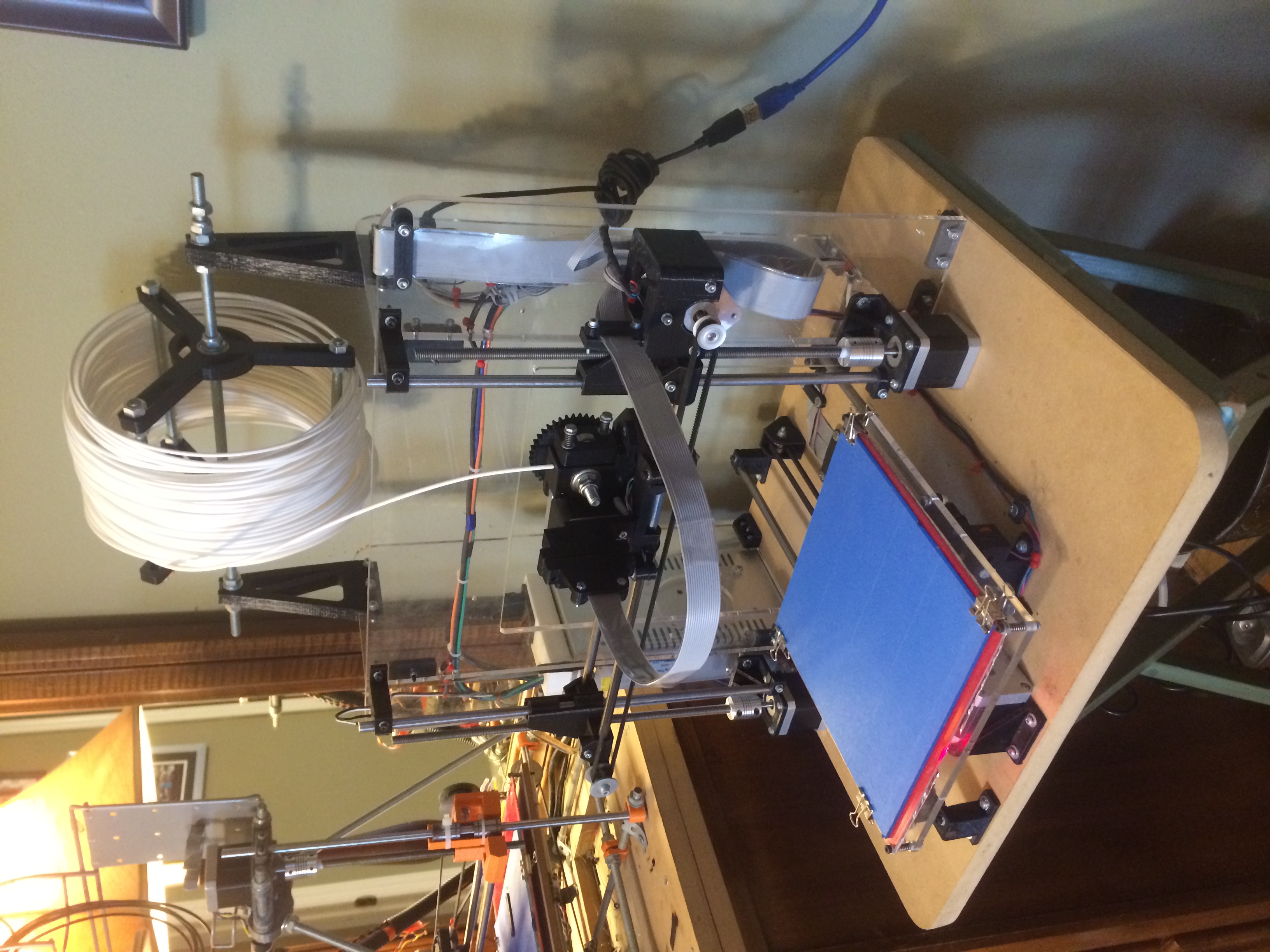
Mendel90 Construction so far - Power Supply on order.
Mendel90 Construction so far - Power Supply on order.
Kapton Polymide tape used to cover the Glass Panels. This is a Polymer, and when heated, adheres well to other Polymers (PLA / ABS).
Kapton Polymide tape used to cover the Glass Panels. This is a Polymer, and when heated, adheres well to other Polymers (PLA / ABS).
Strands of Ribbon Wire Connected to support higher current (1.1A / Cable). Ribbon Cable used for clean repetitious rolling action (like Arcade Machines).
Strands of Ribbon Wire Connected to support higher current (1.1A / Cable). Ribbon Cable used for clean repetitious rolling action (like Arcade Machines).
Hot End threaded into Black PEEK Thermoplastic, which is secured into Wade's Extruder block by 3x Bolts.
Hot End threaded into Black PEEK Thermoplastic, which is secured into Wade's Extruder block by 3x Bolts.
Most of the ribbon cable wiring completed.
Most of the ribbon cable wiring completed.
3D Printed a Quick Serial Connector, so the Extruder may be swapped out (for different resolutions and different plastics).
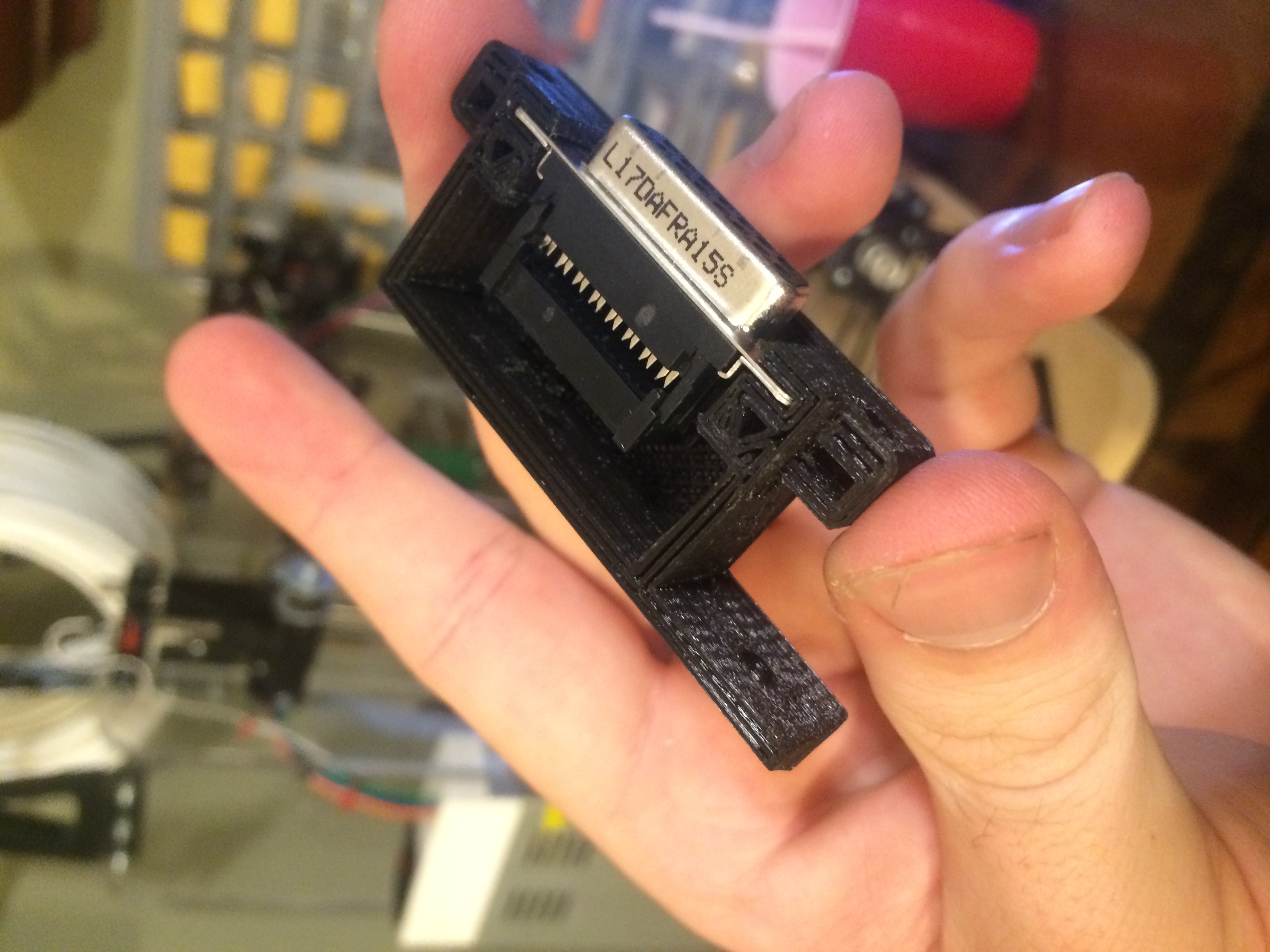
3D Printed a Quick Serial Connector, so the Extruder may be swapped out (for different resolutions and different plastics).
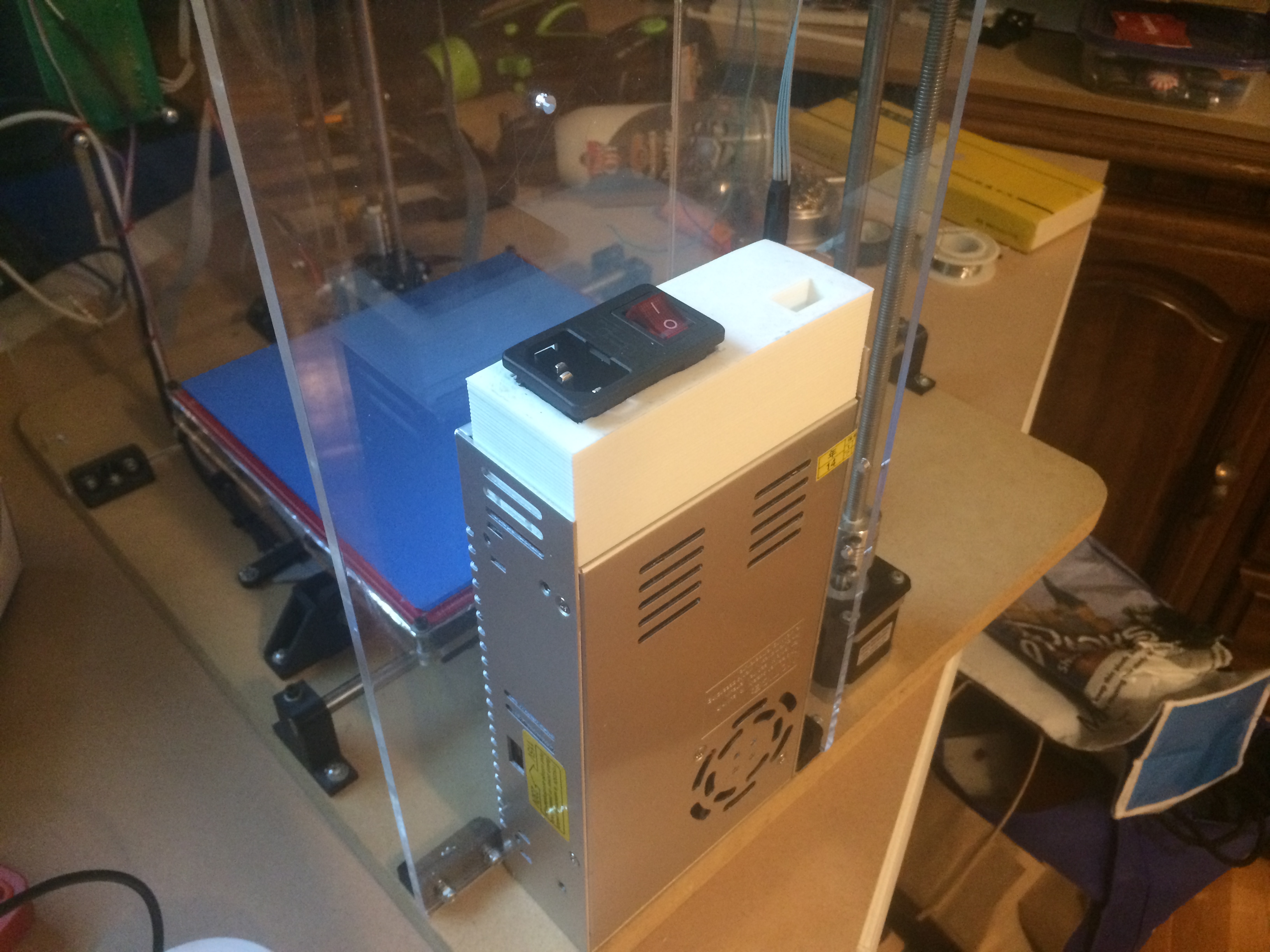
Power Supply mounted through holes drilled in the Acrylic. - Nice and flush.
Power Supply mounted through holes drilled in the Acrylic. - Nice and flush.
Universal IEC Connectors so the Printer may be unplugged. Socket is also Fuse Protected for Safety.
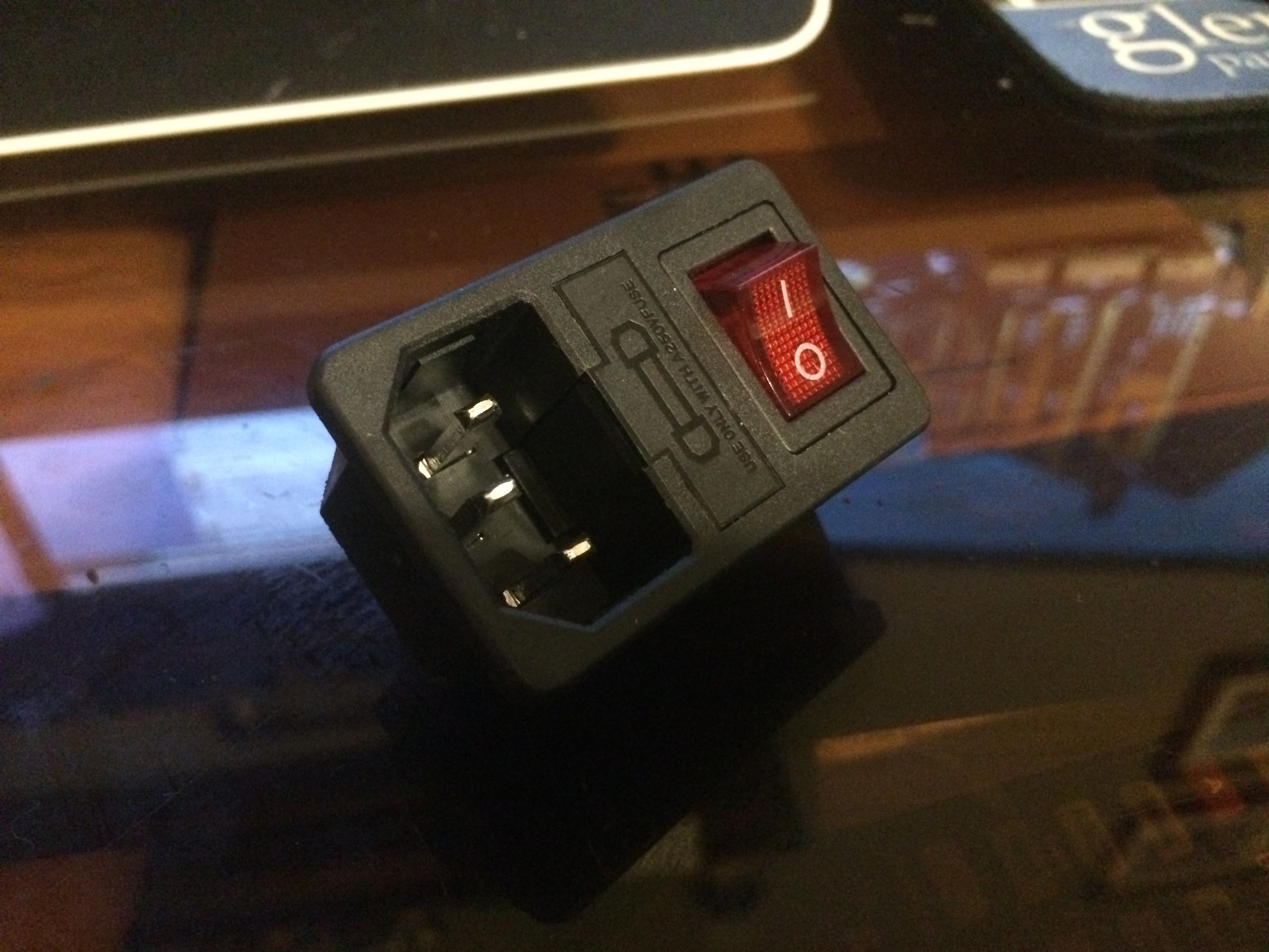
Universal IEC Connectors so the Printer may be unplugged. Socket is also Fuse Protected for Safety.
3D Printed IEC Cage mounted onto the Power Supply, time to install wires.
3D Printed IEC Cage mounted onto the Power Supply, time to install wires.
Heat Shrink Ring Connector Terminals - No Compromise in quality.
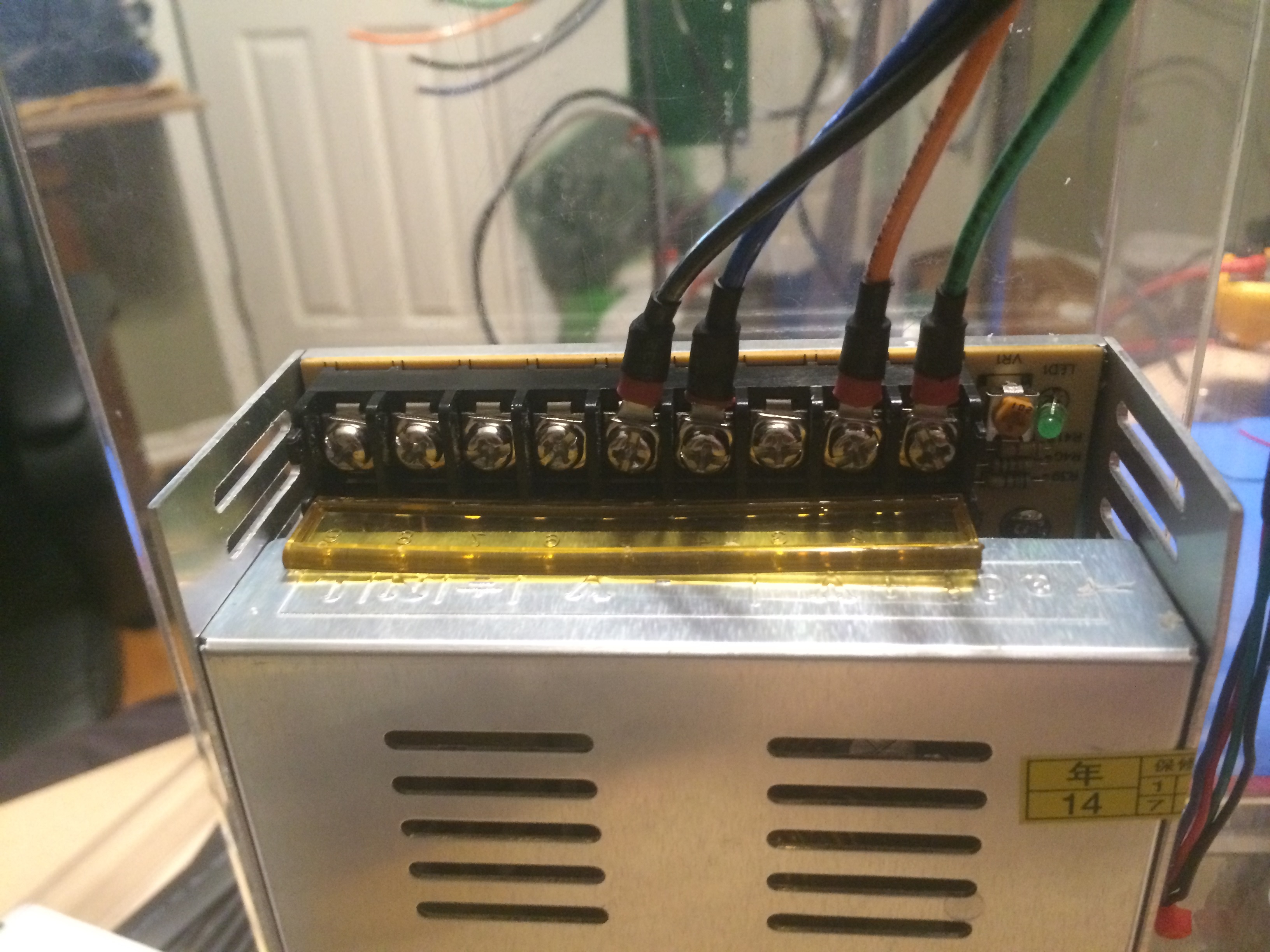
Heat Shrink Ring Connector Terminals - No Compromise in quality.
Enclosure all sealed up, testing fit and voltage.
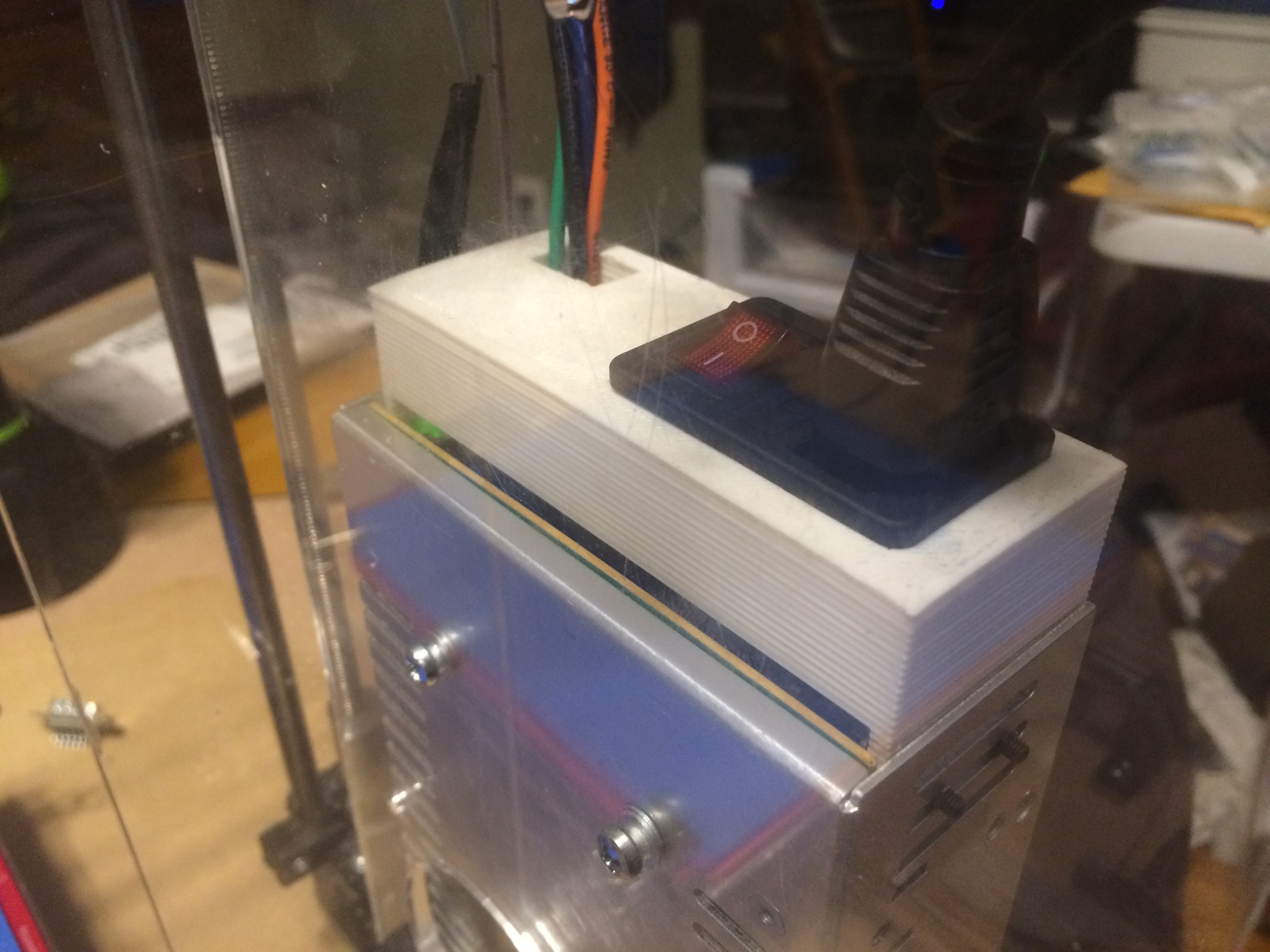
Enclosure all sealed up, testing fit and voltage.
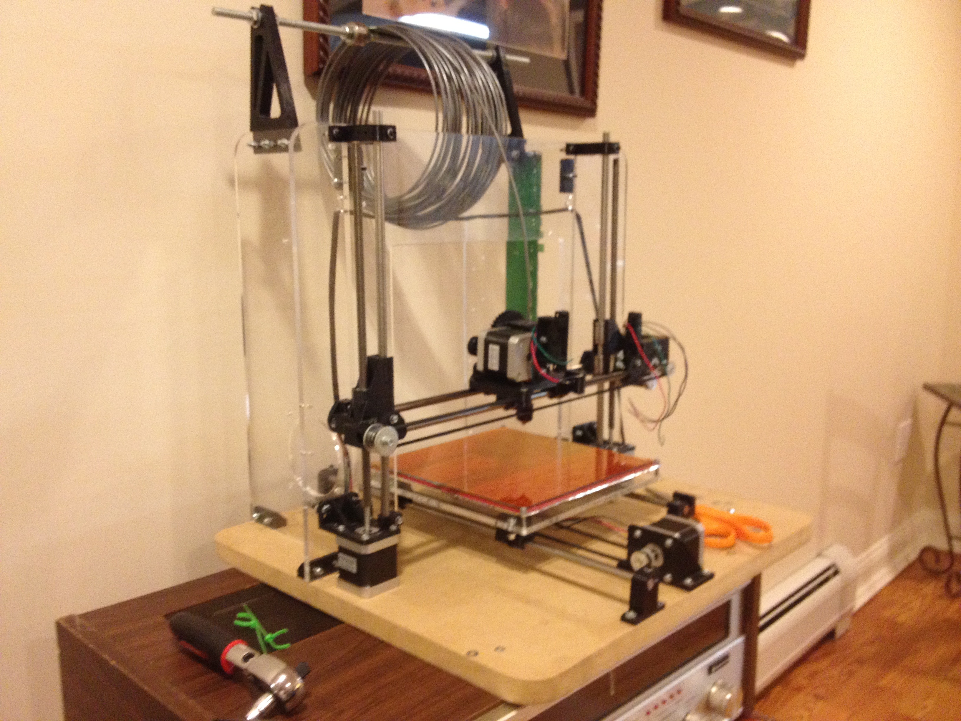
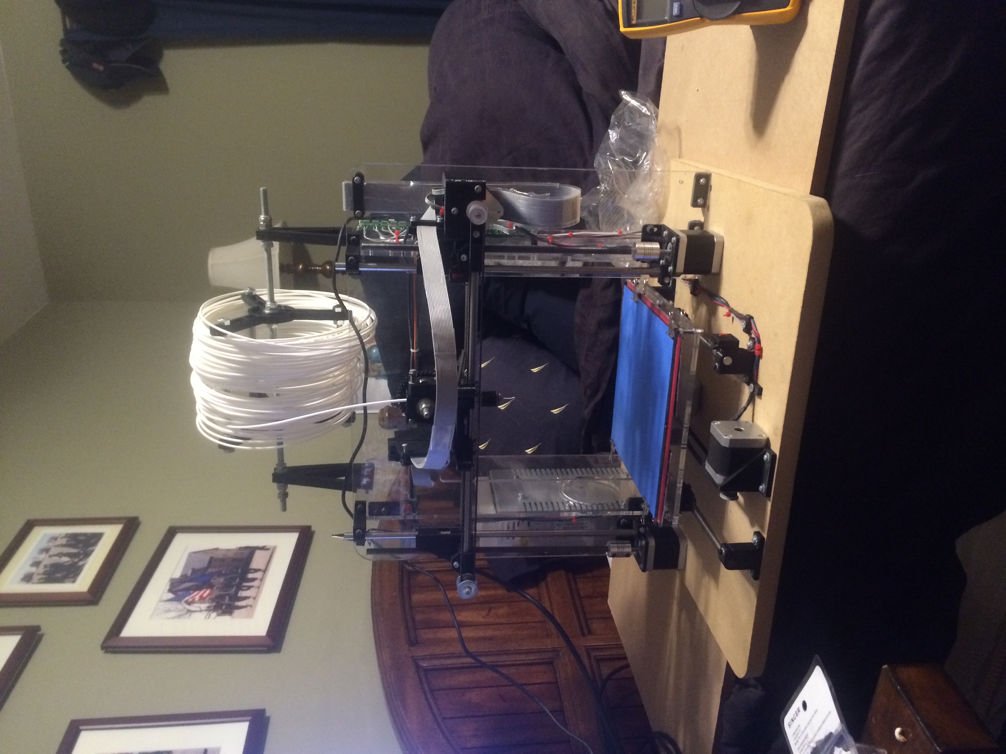
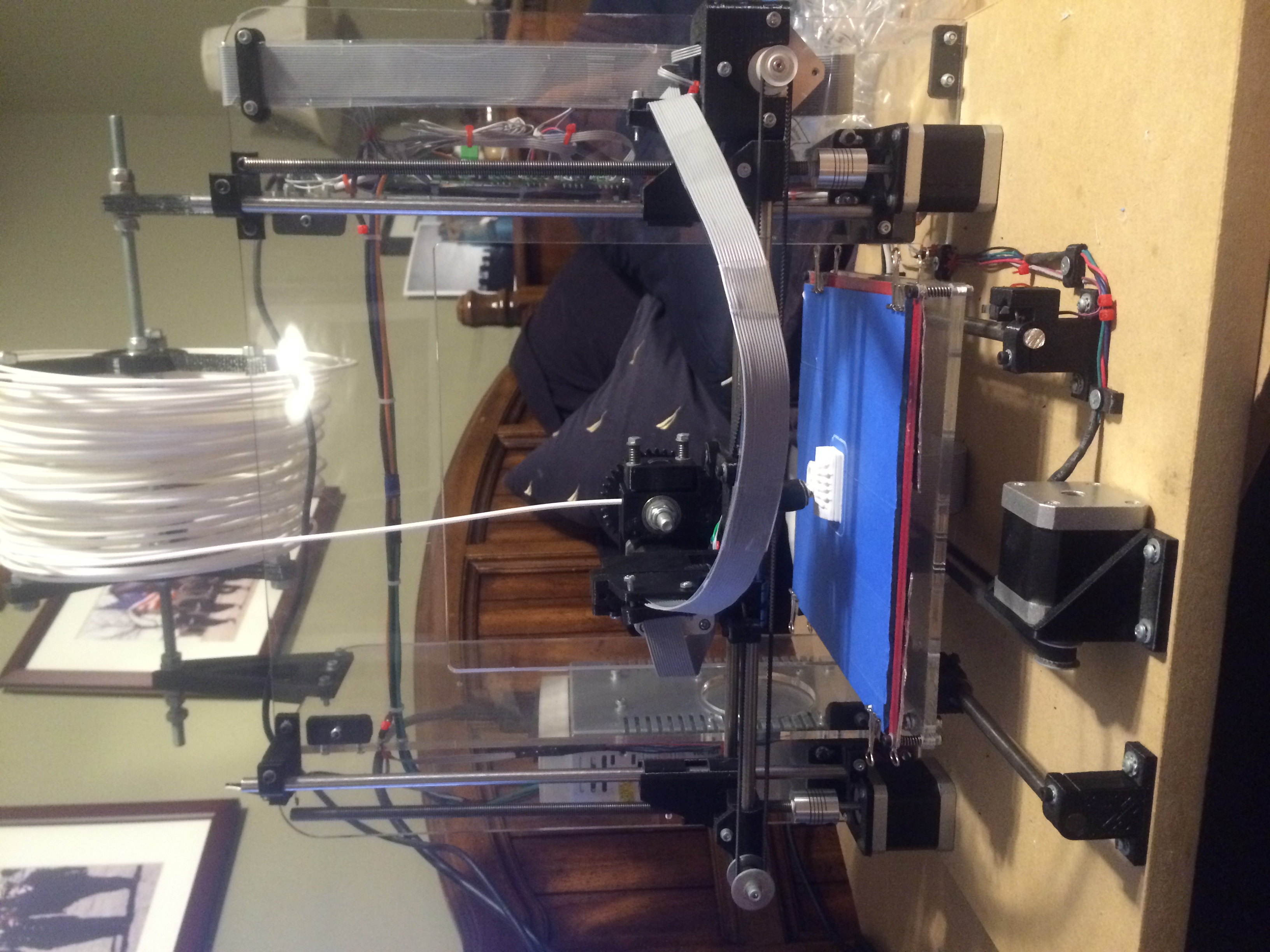
The Mendel90 on the Left, and the Prusa i2 on the right.
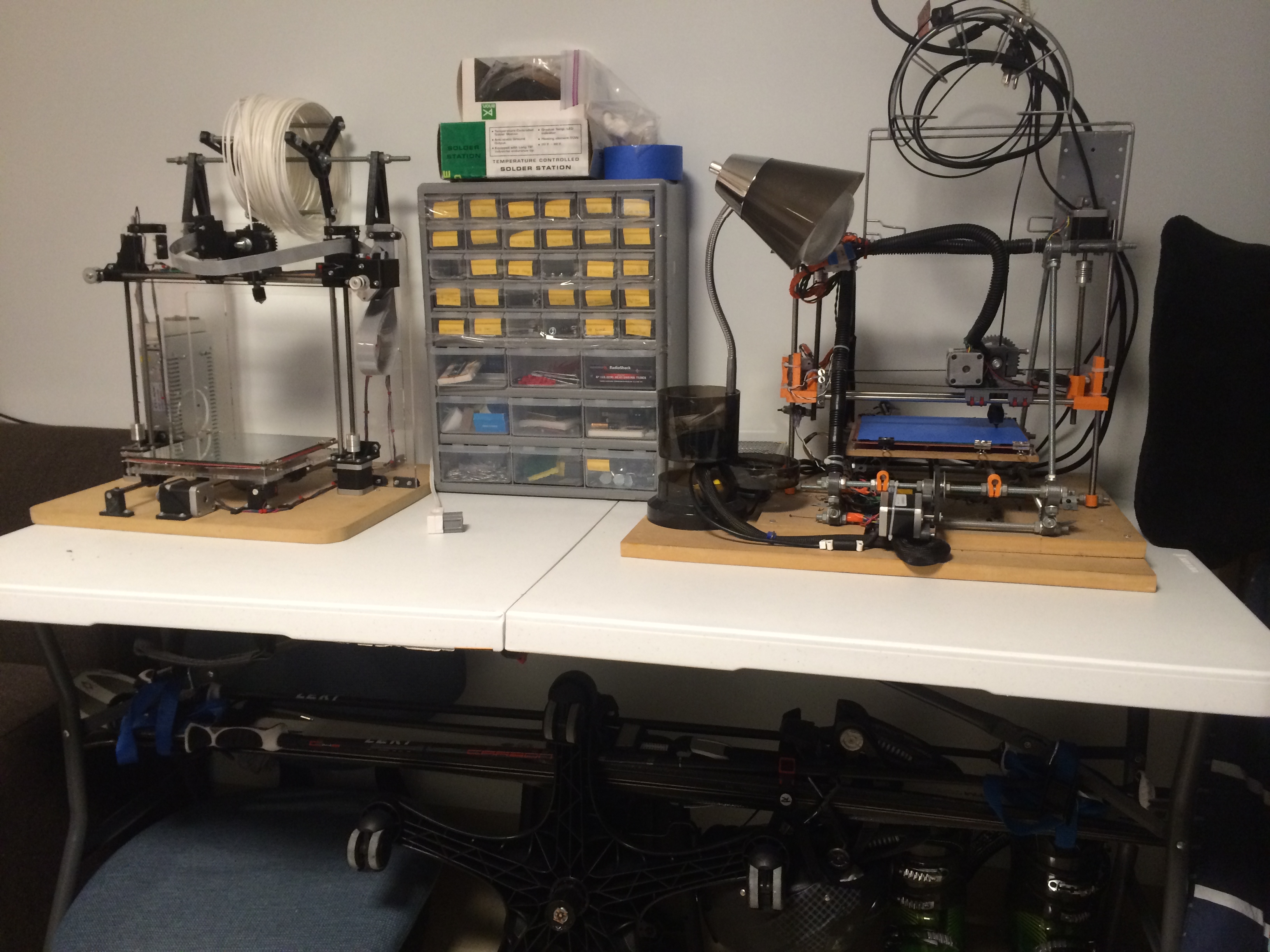
The Mendel90 on the Left, and the Prusa i2 on the right.
Prusa i2 on the left, and the Mendel90 on the right, Mid Construction.
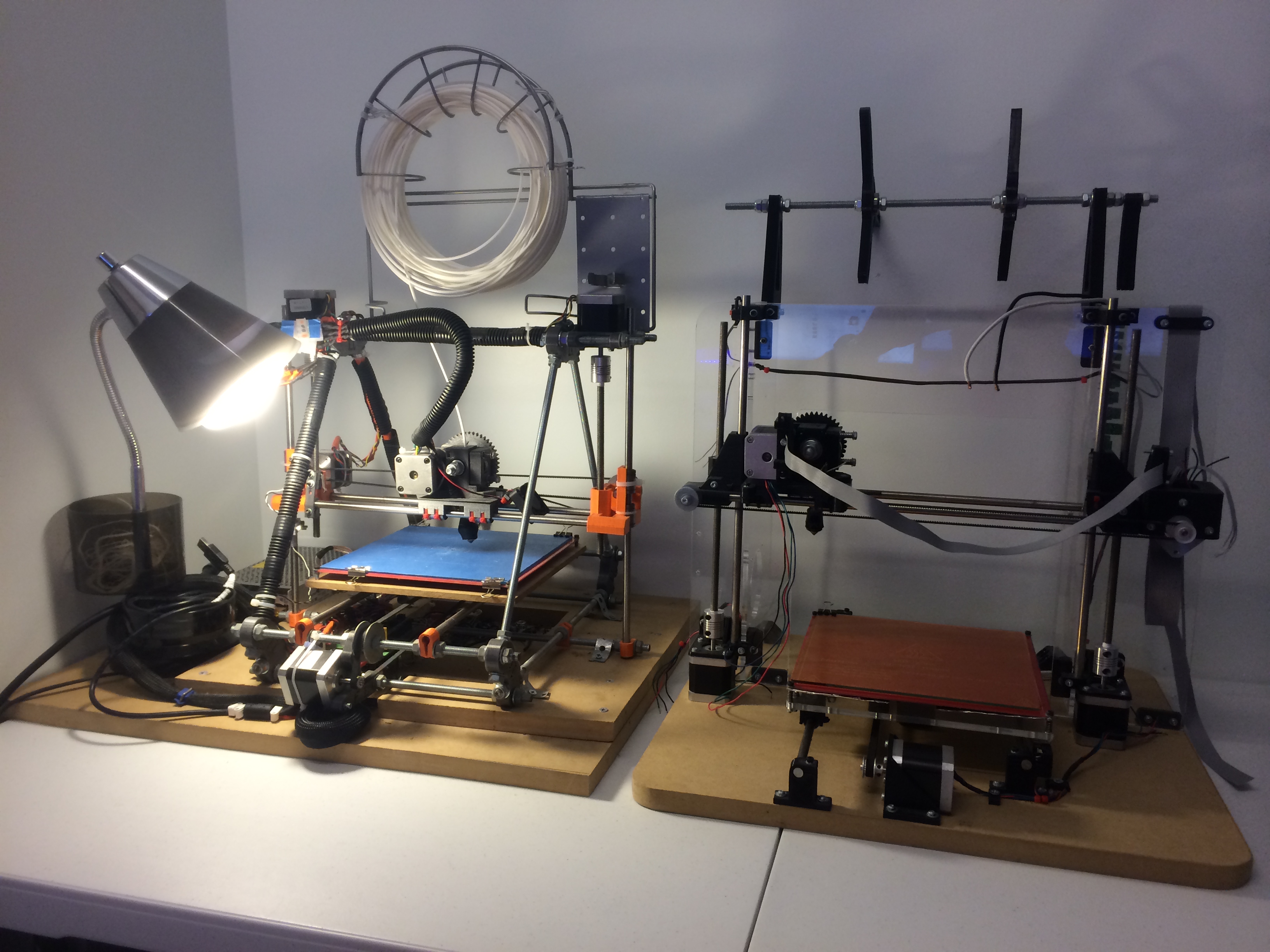
Prusa i2 on the left, and the Mendel90 on the right, Mid Construction.
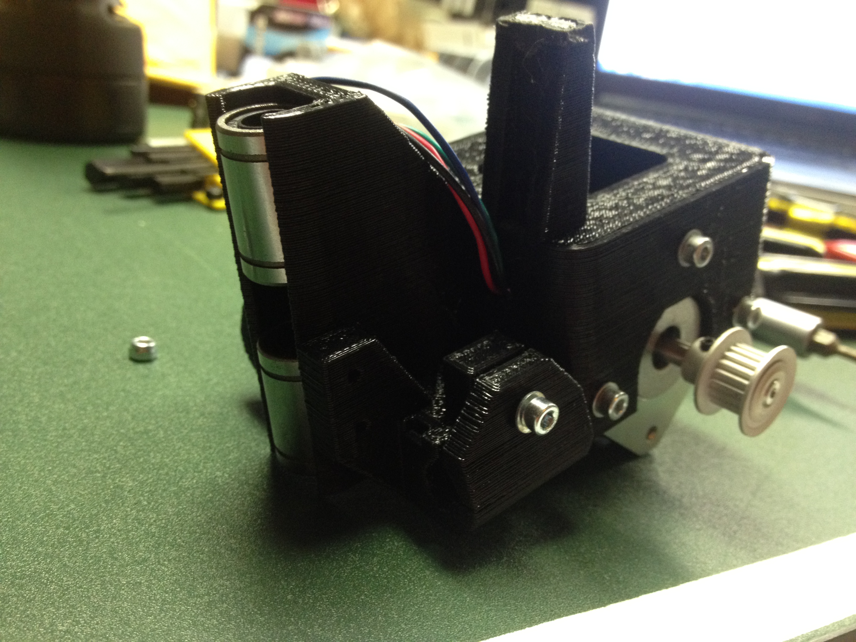
Serial Quick-Connects mounted onto the Stepper Motor / Wade Extruder Block.
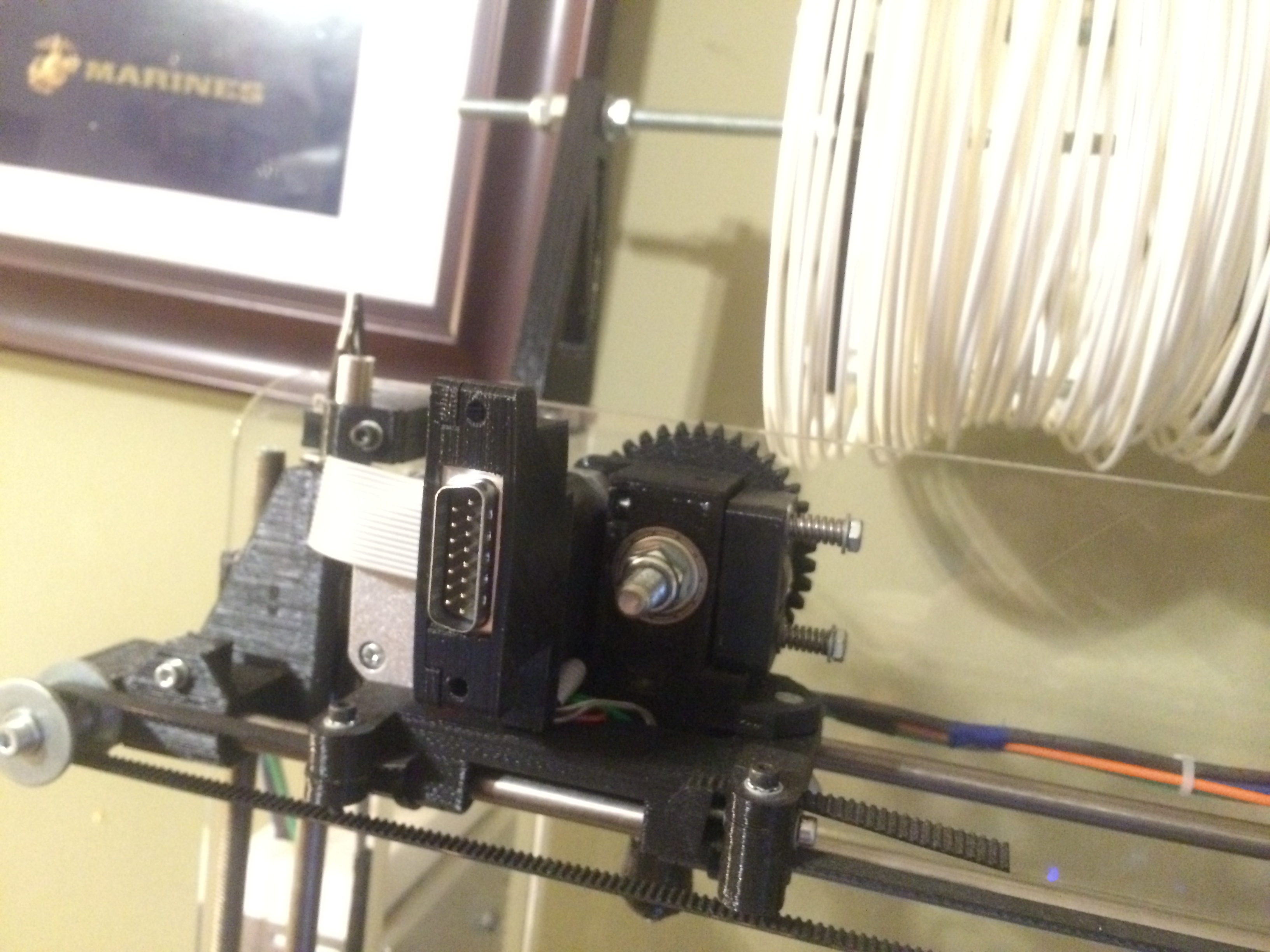
Serial Quick-Connects mounted onto the Stepper Motor / Wade Extruder Block.
Female End of Connector Wired up, disconnected from the Extruder.
Female End of Connector Wired up, disconnected from the Extruder.
Male and Female Connectors combined, showing nice linear rolling movement of Ribbon Cable extending outwards.
Male and Female Connectors combined, showing nice linear rolling movement of Ribbon Cable extending outwards.
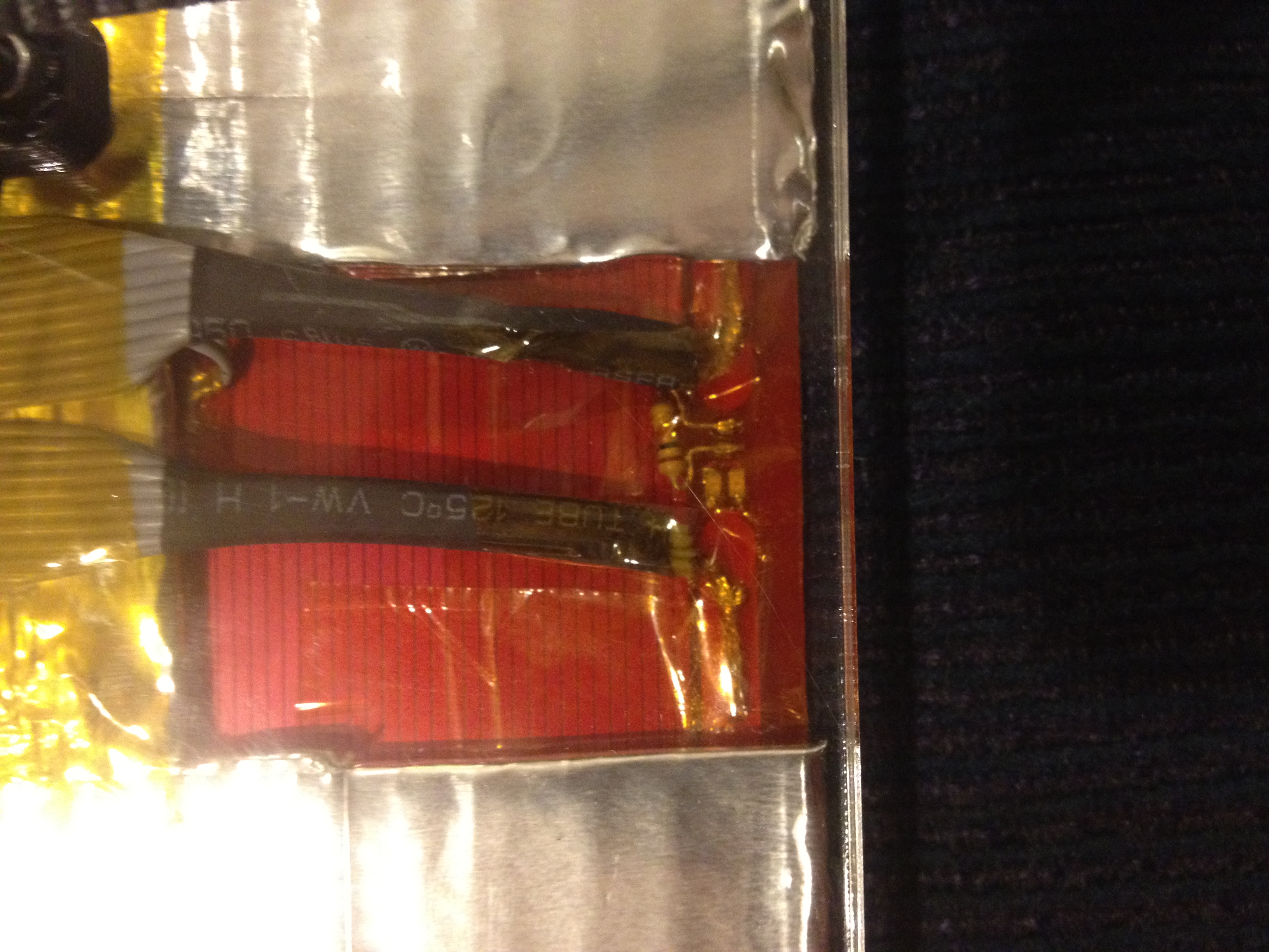
Arduino / AtMega 1284 Chip Soldered onto a Pololu PCB Screw-Terminal Breakout Board. Wiring shown as well.
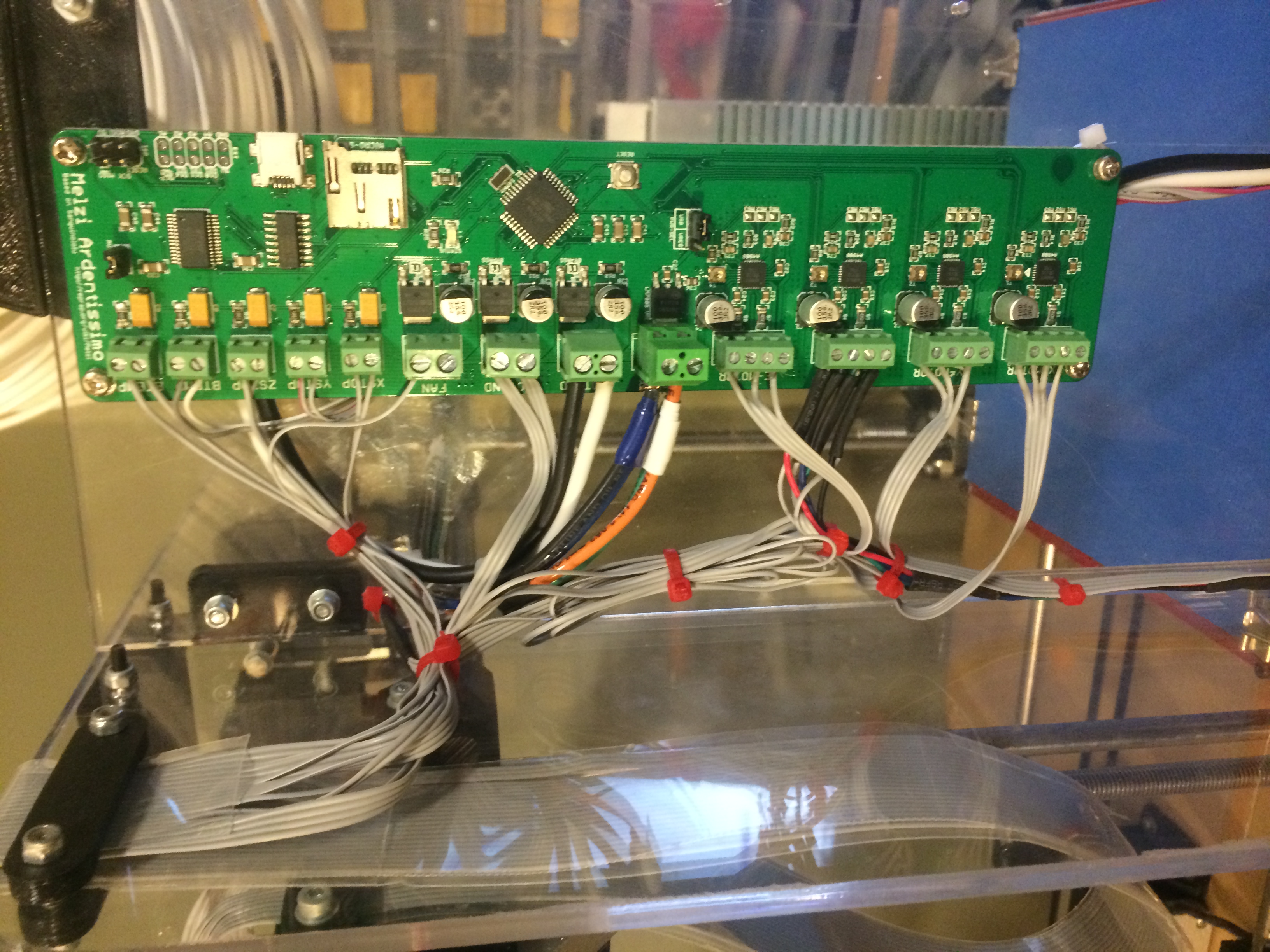
Arduino / AtMega 1284 Chip Soldered onto a Pololu PCB Screw-Terminal Breakout Board. Wiring shown as well.
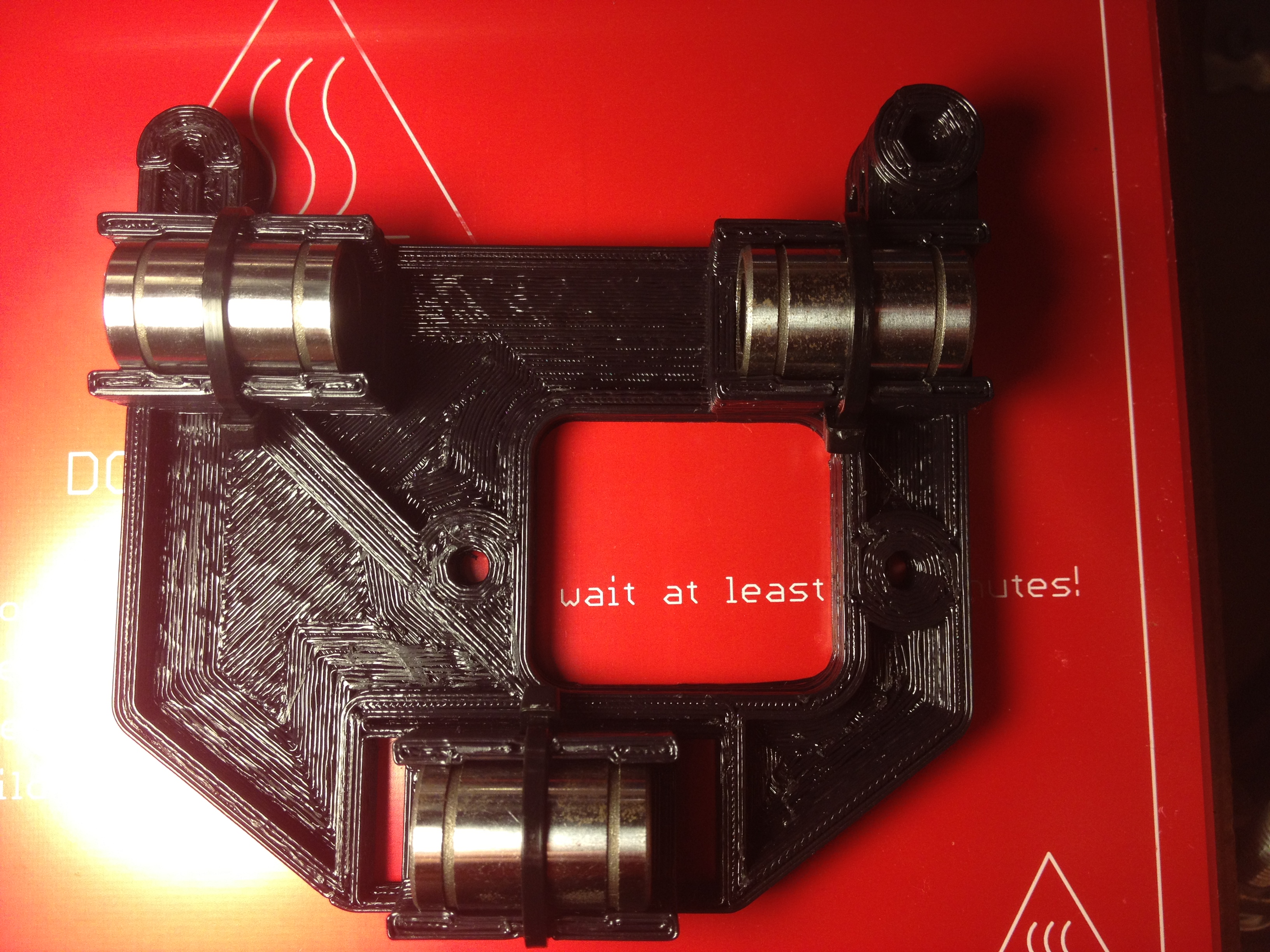
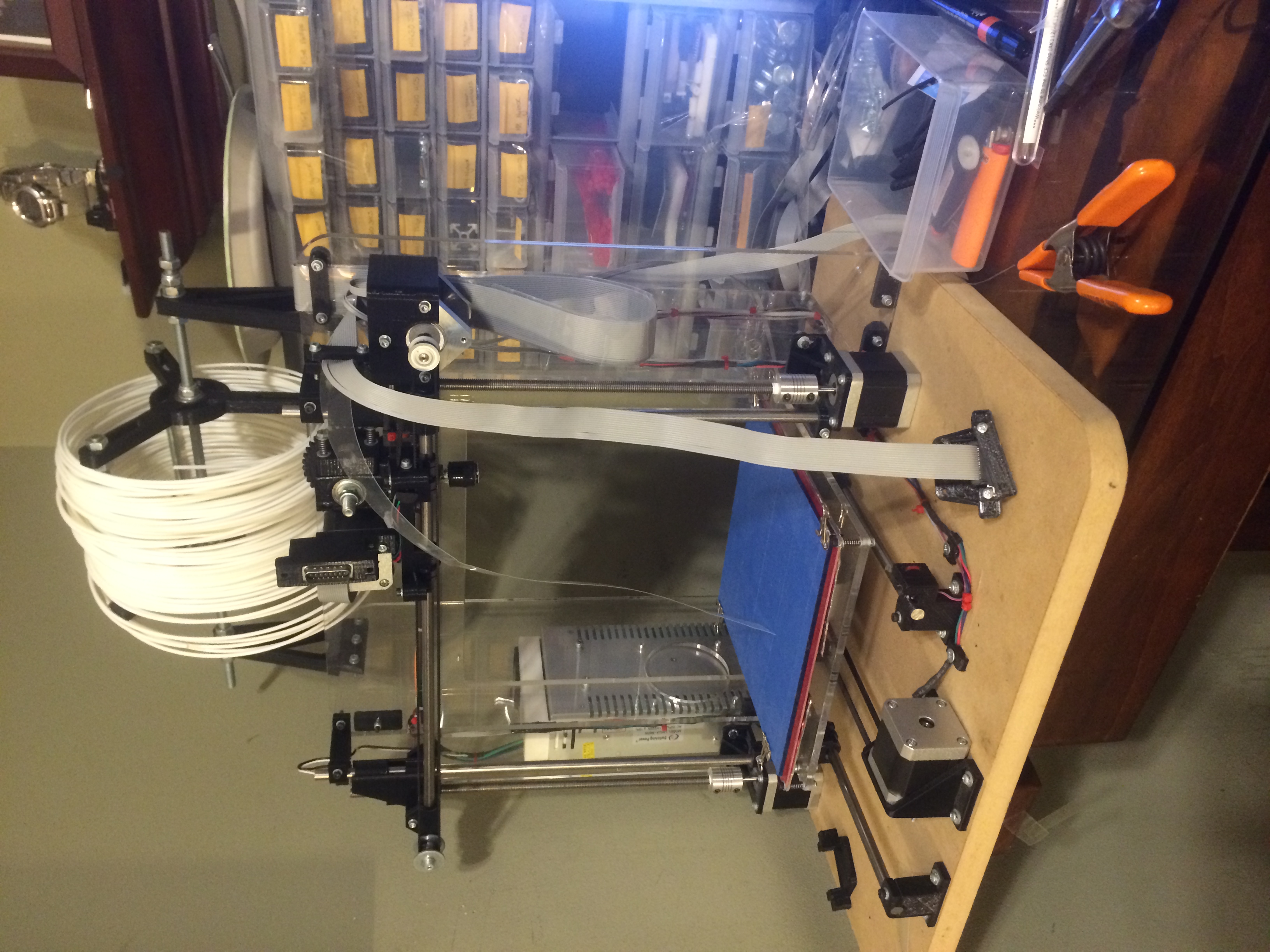
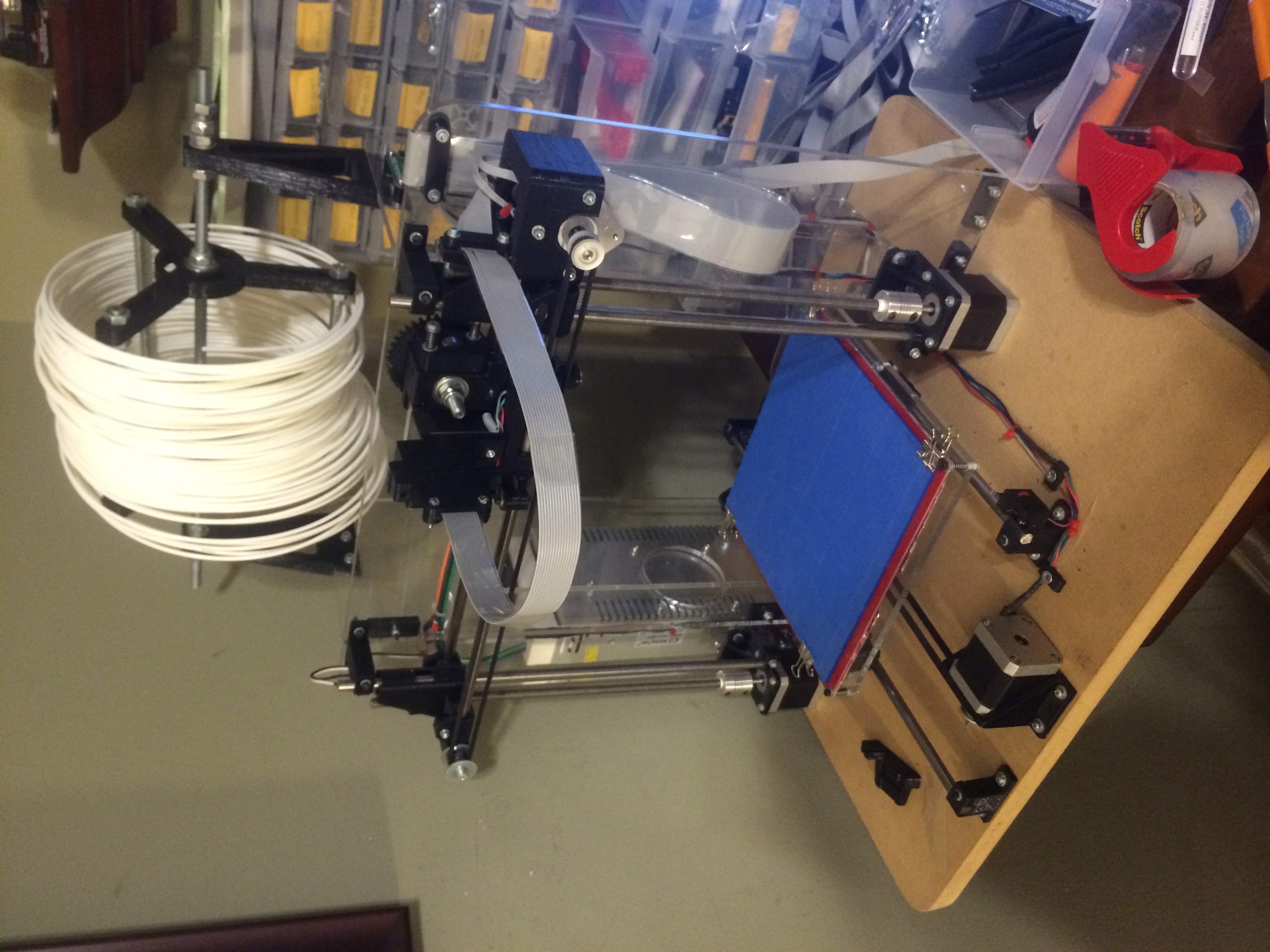
Preparing the Printer for First calibration prints!
Preparing the Printer for First calibration prints!
Plastic running through the extruder heating up.
Plastic running through the extruder heating up.
After Minor Temperature Adjustments, Printer is ready to start first print - Go!
After Minor Temperature Adjustments, Printer is ready to start first print - Go!
Base of a Left-Facing Owl, Beautiful Print Quality, especially for a first print.
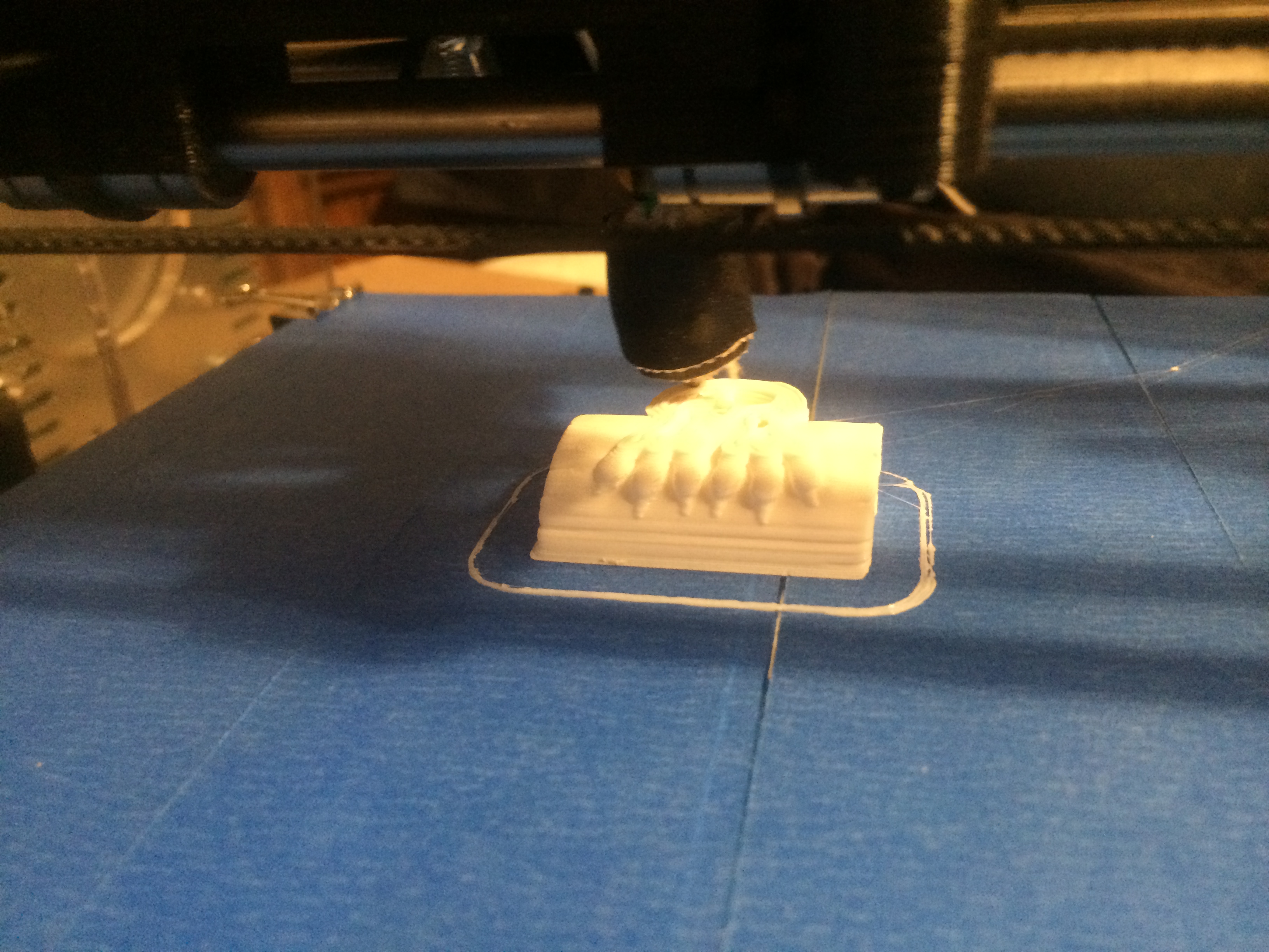
Base of a Left-Facing Owl, Beautiful Print Quality, especially for a first print.
Action Shot! Printer is printing the Owl.
Action Shot! Printer is printing the Owl.
Owl beautifully printed - extremely satisfied with the results. Overhangs and everything look great as well - especially for a fanless (for now) design.
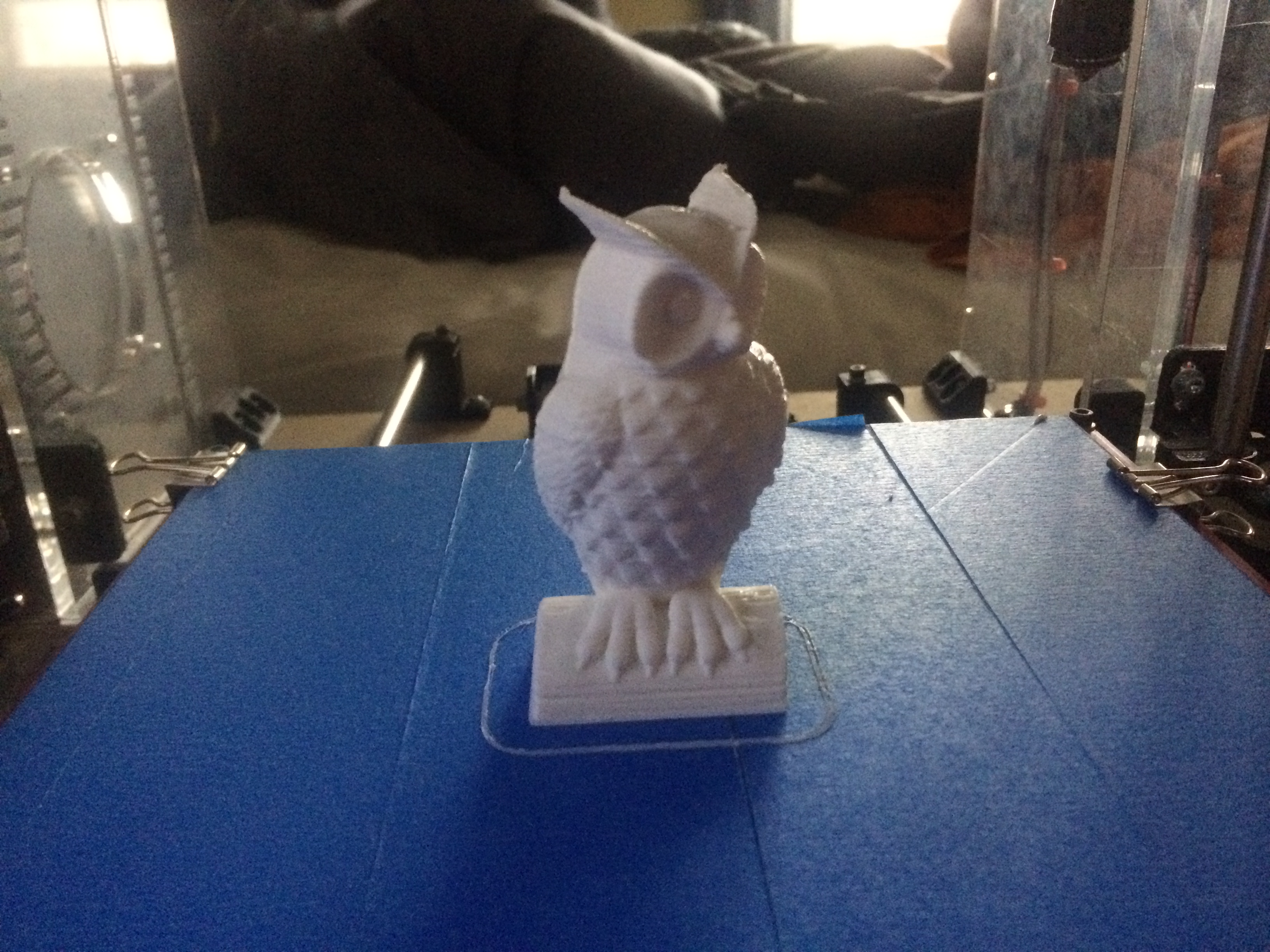
Owl beautifully printed - extremely satisfied with the results. Overhangs and everything look great as well - especially for a fanless (for now) design.
Preparing Print number 2! Squirrel!
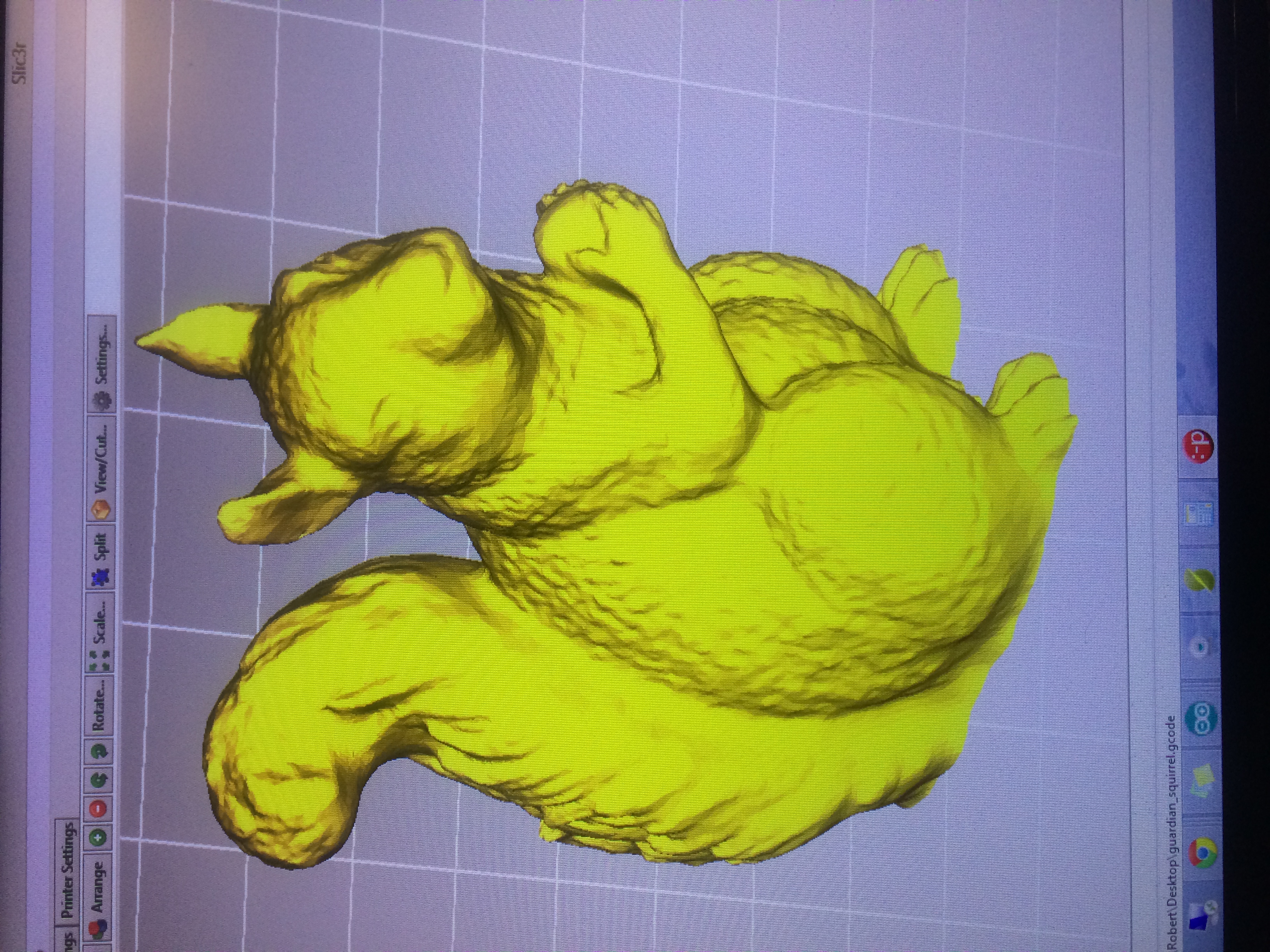
Preparing Print number 2! Squirrel!
Success!
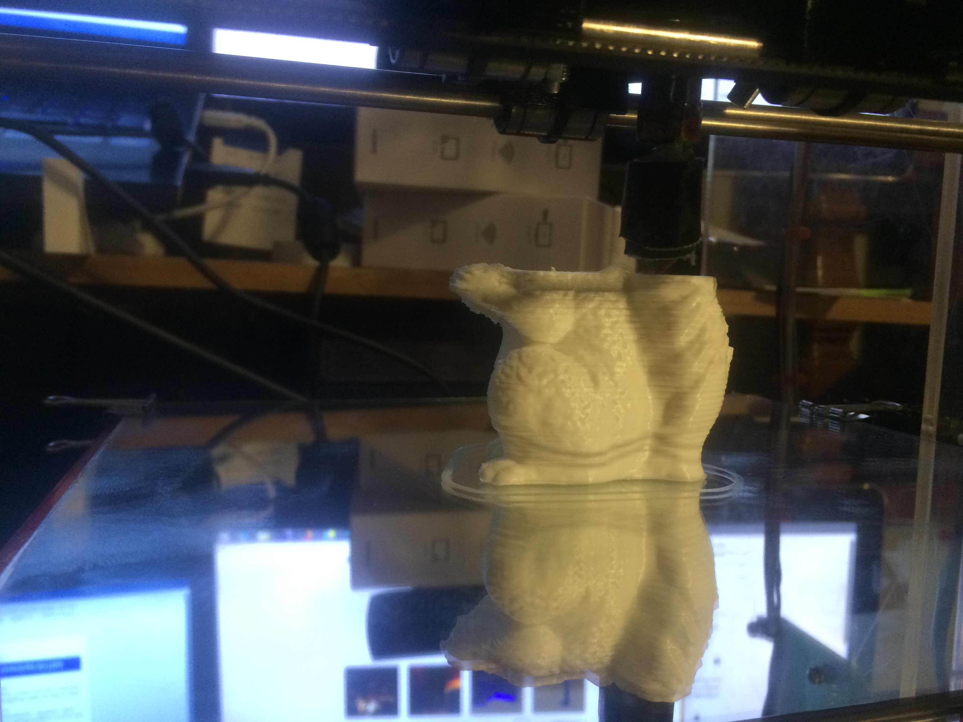
Success!